Achieving dimensional accuracy is the result of meticulously managing plastic shrinkage throughout the entire injection molding production cycle. In precision manufacturing, you often face the frustration of parts that do not fit their intended assemblies because they contracted more than expected. This creates a ripple effect of quality failures, wasted material, and expensive tooling rework that can stall your project for weeks. By understanding the variables behind plastic shrinkage , you can design more robust molds and select process parameters that guarantee consistency from the first shot to the last.
What exactly is plastic shrinkage in molding?
Plastic shrinkage is the physical reduction in the volume of a polymer part as it transitions from a high-energy molten state into a stable solid within the mold. You must account for this volumetric change to ensure that your final part dimensions align with your critical design specifications.
Defining volume reduction during cooling
Polymers transition from a high-energy melt to a stable solid state, which naturally causes the material density to increase. The result?
- Molecular chains pack closer together.
- Specific volume decreases significantly.
- Internal pressures shift.
This contraction occurs primarily during the cooling phase before the part is ejected. Believe it or not, this is a universal law of thermodynamics in molding.
- Cooling rates vary by part thickness.
- Mold temperature influences molecular arrangement.
- Crystalline structures pack more tightly.
How does it differ from drying shrinkage?
Thermal contraction during cooling is an immediate physical change, whereas drying shrinkage in hygroscopic materials occurs over time due to moisture loss. You will find that these two phenomena require entirely different mitigation strategies. But wait, there’s more.
- Thermal shrinkage is process-driven.
- Drying shrinkage is environmentally dependent.
- Material grade dictates the response.
Post-molding stability is only achieved when you stabilize the moisture content of the part. That’s just the beginning.
- Nylons are particularly susceptible.
- Ambient humidity levels must be controlled.
- Stabilization can take 24 to 48 hours.
Key Takeaway: Understanding the distinction between thermal contraction and moisture-related changes prevents misdiagnosing dimensional errors.
| Parameter | Description | Primary Driver | |
|---|---|---|---|
| Plastic Shrinkage | Volume loss during the cooling phase | Thermal contraction | |
| Drying Shrinkage | Dimensional change due to moisture loss | Environmental RH |
This table clarifies that while both lead to size reduction, the engineering solution for each differs based on the root cause.
Why does plastic shrinkage affect part quality?
Controlling plastic shrinkage is vital because it determines the final dimensional tolerances and the structural integrity of your finished plastic components. When these rates are unpredictable, you encounter assembly failures and aesthetic defects that can ruin a product’s market value.
Impact on dimensional tolerances
Precision fits between mating components rely on the mold being sized larger than the part to account for expected contraction. The result?
- Interference fits become loose.
- Snap-fits may fail to engage.
- Threaded sections may bind or strip.
You cannot achieve a ±0.05mm tolerance if your material exhibits a 2% variation in size after cooling. But that’s not all.
- Tooling must be oversized appropriately.
- Gate location shifts dimensions locally.
- Wall thickness affects linear results.
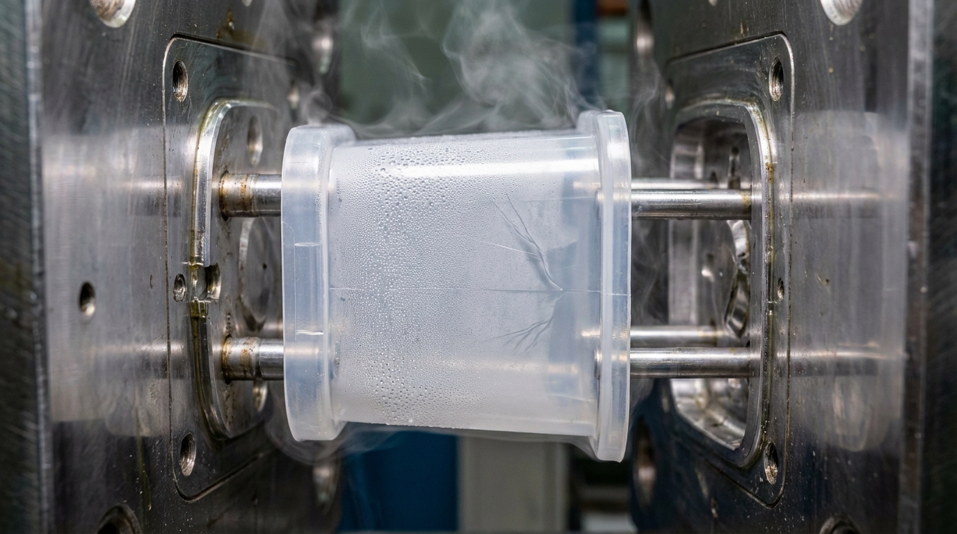
Structural integrity and surface defects
Non-uniform contraction creates internal stresses that pull the outer surfaces inward, leading to unsightly sink marks or internal voids. Think about it.
- Thick ribs pull on thin walls.
- Warping occurs as stresses relax.
- Surface finish loses its uniformity.
These defects are not just cosmetic; they often indicate weak points where the part might fail under mechanical load. Here is the kicker.
- Internal voids reduce load capacity.
- Warping creates assembly stress.
- Residual stress leads to premature cracking.
Key Takeaway: Dimensional accuracy is the primary victim of unmanaged contraction, leading to both cosmetic and functional failures.
| Defect | Cause | Impact | |
|---|---|---|---|
| Warpage | Non-uniform contraction | Part misalignment | |
| Sink Marks | Localized high shrinkage | Aesthetic failure |
Effective quality control requires balancing these visual and structural impacts through careful material and process selection.
What causes plastic shrinkage during injection?
Plastic shrinkage is caused by the thermal contraction of the polymer chains as they lose heat and the specific molecular orientation created during the high-pressure injection phase. You can visualize this as a two-part process involving temperature drops and the physical stretching of the material.
The role of thermal contraction
As the melt temperature drops to the mold temperature, the distance between polymer molecules decreases as their kinetic energy dissipates.
The result?
- The material becomes denser.
- Linear dimensions shorten.
- Volumetric mass increases.
The coefficient of thermal expansion for most polymers is high, meaning even small temperature changes result in measurable size differences. But that’s not all.
- Melt temperature dictates starting volume.
- Mold temperature controls the cooling curve.
- Ambient air affects post-mold cooling.
How molecular orientation impacts volume
The flow of molten plastic into the cavity stretches polymer chains in the direction of the flow, leading to different contraction rates across the part. The result?
- Shrinkage is higher along the flow.
- Transverse shrinkage is usually lower.
- Anisotropic behavior causes warping.
You will notice that complex geometries with winding flow paths exhibit the most unpredictable dimensional shifts. That’s just the beginning.
- Gate placement determines flow direction.
- Injection speed affects chain stretching.
- Packing pressure helps “freeze” orientation.
Key Takeaway: Thermal cooling and molecular stretching work together to pull the part away from the cavity walls.
| Factor | Influence Level | Mechanism | |
|---|---|---|---|
| Cooling Rate | High | Impacts crystallinity levels | |
| Flow Path | Medium | Dictates chain orientation |
Thermal contraction is the dominant driver, but molecular orientation is what usually causes the part to lose its intended shape.
How does material choice impact plastic shrinkage?
Selecting a polymer with the right crystalline structure is the most significant decision you can make to manage plastic shrinkage effectively. Your choice between amorphous and semi-crystalline resins dictates the baseline stability of every part you produce.
Semi-crystalline vs. amorphous polymers
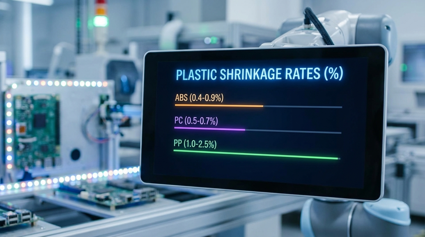
Semi-crystalline materials like Polypropylene have highly organized molecular structures that pack tightly upon cooling, resulting in significantly higher shrinkage rates.
The result?
- Shrinkage can exceed 2.0%.
- Dimensions are harder to predict.
- Cooling time is more critical.
Conversely, amorphous materials like ABS or Polycarbonate remain disorganized and exhibit much lower, more predictable shrinkage. But that’s not all.
- ABS shrinks roughly 0.5%.
- PC offers excellent stability.
- Tolerances are easier to hold.
Do additives and fillers reduce the effect?
Integrating glass fibers or mineral fillers into the resin acts as a mechanical restraint that physically prevents the polymer matrix from contracting. The result?
- Linear shrinkage is cut in half.
- Stiffness increases significantly.
- Thermal stability improves.
You must be careful, however, as these fibers also increase the anisotropy of the part, which can lead to specific warping patterns. Here is the kicker.
- Fibers align with the flow.
- Transverse stability is less affected.
- Part weight increases slightly.
Key Takeaway: Resin chemistry is the foundation of dimensional control, with amorphous materials offering the highest precision.
| Material Type | Typical Shrinkage (%) | Example Resins | |
|---|---|---|---|
| Amorphous | 0.3% – 0.8% | ABS, Polycarbonate | |
| Semi-Crystalline | 1.0% – 2.5% | PP, Nylon, PE |
Choosing an amorphous resin is the fastest way to simplify your dimensional accuracy challenges if the application allows.
Can mold design control plastic shrinkage levels?
You can control plastic shrinkage through intelligent mold design by optimizing gate placement to ensure the cavity is fully packed with material before it solidifies. The physical layout of the tool is your primary defense against uneven contraction and warping.
Optimizing gate location and size
The gate is the entry point that allows the machine to “pack” extra material into the cavity to compensate for the volume lost during cooling. The result?
- Pressure is maintained longer.
- Sink marks are minimized.
- Dimensions stay closer to the tool.
If your gate freezes too early, the machine cannot add more material to offset the natural contraction. But that’s not all.
- Larger gates delay freeze-off.
- Thick sections need direct gating.
- Flow length affects final pressure.
Importance of uniform wall thickness
Designing parts with consistent wall thickness ensures that the entire part cools at the same rate, preventing the “pull” of thicker sections on thinner ones. The result?
- Internal stresses are balanced.
- Warping is greatly reduced.
- Cooling cycles are optimized.
You should use coring and ribs to maintain structural strength without creating the heavy masses that drive excessive shrinkage. That’s just the beginning.
- Avoid sharp thickness transitions.
- Use radii to smooth flow.
- Balance cooling channel distances.
Key Takeaway: Tool design acts as the mechanical “envelope” that restricts how much and where the plastic can move as it cools.
| Design Element | Strategy | Benefit | |
|---|---|---|---|
| Gate Size | Increase for thick parts | Better packing pressure | |
| Cooling Channels | Even distribution | Uniform contraction |
Uniformity in cooling and pressure distribution is the secret to a dimensionally stable part.
What process settings influence plastic shrinkage?
Optimizing the interaction between pressure, temperature, and time is the most effective way for you to reduce plastic shrinkage once the mold is already built. You must fine-tune these variables to ensure the polymer reaches its maximum possible density before it leaves the press.
Balancing pack pressure and hold time
Higher packing pressure forces more molecules into the cavity to occupy the space that would otherwise be lost to contraction.
The result?
- Part density increases.
- Linear shrinkage decreases.
- Dimensions become more stable.
You must hold this pressure until the gate solidifies, otherwise, the molten plastic will “backflow” out of the cavity. But wait, there’s more.
- Hold time must exceed gate freeze.
- Excessive pressure can cause sticking.
- Uniform pressure reduces warpage.
Effect of melt and mold temperatures
While a higher melt temperature expands the plastic initially, a higher mold temperature allows the polymer to relax more effectively, which can ironically increase final shrinkage. The result?
- Molecular chains organize better.
- Crystallinity increases in resins.
- Internal stresses are relieved.
Finding the “sweet spot” for mold temperature is a balancing act between cycle time and dimensional stability. Here is the kicker.
- Hotter molds improve surface finish.
- Colder molds freeze parts faster.
- Rapid cooling traps more stress.
Key Takeaway: Process control is the final lever you pull to achieve the tolerances required for high-precision assemblies.
| Variable | Change | Resulting Shrinkage | |
|---|---|---|---|
| Pack Pressure | Increase | Decrease | |
| Mold Temperature | Increase | Increase (usually) |
Pressure is your most powerful tool for “forcing” the plastic to stay the right size, while temperature dictates the final quality of the solid.
How to calculate the plastic shrinkage rate?
Calculating the plastic shrinkage rate involves comparing the dimensions of the cold part to the dimensions of the mold cavity using a standard percentage formula. You must use this calculation to size your tooling correctly before a single piece of steel is cut.
Using standard shrinkage formulas
The basic formula used by engineers is S = (Dm - Dp) / Dm , where Dm is the mold dimension and Dp is the final part dimension. The result?
- You get a predictable ratio.
- Tooling can be oversized accurately.
- Material data sheets are validated.
You should always measure parts at least 24 hours after molding to ensure they have reached thermal and moisture equilibrium. But that’s not all.
- Digital calipers offer quick checks.
- CMM provides 3D verification.
- Averages reduce measurement error.
Why do flow directions matter in results?
Shrinkage is rarely the same in all directions, so you must calculate rates for both the direction of flow and the transverse direction. The result?
- Elliptical holes are prevented.
- Rectangular parts stay square.
- Warping risks are identified.
Complex parts with varied wall thicknesses will require different shrinkage factors for different regions. That’s just the beginning.
- Ribs shrink differently than walls.
- Bosses create localized spots.
- Flow paths dictate the “stretch.”
Key Takeaway: A single shrinkage value is an oversimplification; professional engineers calculate directional rates for better precision.
| Input | Source | Purpose | |
|---|---|---|---|
| Dm (Mold Dim) | Tooling Specs | Baseline reference | |
| Dp (Part Dim) | CMM Measurement | Final achieved size |
Accurate data collection from T1 samples allows you to make precise “steel safe” adjustments to the mold.
Does DFM analysis prevent plastic shrinkage issues?
A comprehensive DFM analysis identifies high-risk geometries prone to plastic shrinkage before you commit to the manufacturing phase. By simulating the flow and cooling of the material, you can see where “shrink hotspots” will occur on your digital model.
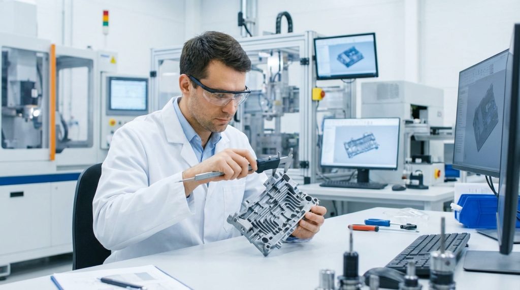
Identifying high-risk areas in CAD
Design for Manufacturability reviews flag features like heavy bosses or thick intersections that will naturally contract more than the surrounding areas.
The result?
- You can thin out heavy areas.
- Sink marks are predicted early.
- Assembly clearances are adjusted.
You save thousands of dollars by making these changes in the software rather than recutting a hardened steel mold. But that’s not all.
- Rib-to-wall ratios are optimized.
- Draft angles are checked.
- Gate locations are simulated.
Simulating material flow for better results
Modern Moldflow simulation software provides a visual map of how the plastic will pack and where the volumetric shrinkage will be highest. The result?
- Warping trends become visible.
- Cooling time is estimated.
- Vents are placed effectively.
This data allows you to adjust the design to “steer” the shrinkage away from critical functional surfaces. Here is the kicker.
- It reduces the number of T-trials.
- It guarantees faster time-to-market.
- It ensures quality from Shot 1.
Key Takeaway: Virtual testing is the most cost-effective way to ensure your part design survives the physics of the molding process.
| DFM Check | Potential Issue | Recommended Solution | |
|---|---|---|---|
| Wall Analysis | Heavy sections | Core out or add ribs | |
| Gate Analysis | Premature freeze | Move to thicker area |
Identifying these issues early prevents 80% of the dimensional problems found during production.
Can fiber reinforcement limit plastic shrinkage?
Using fiber-reinforced resins is a proven method to reduce plastic shrinkage because the stiff fibers provide a structural “skeleton” that resists the polymer’s urge to contract. You will find this particularly useful for parts that require high dimensional stability under varying temperatures.
How fibers restrain volumetric changes
Glass or carbon fibers do not contract like the polymer matrix does, meaning they physically hold the material in place as it cools. The result?
- Linear shrinkage drops by 50-70%.
- Thermal expansion is lowered.
- Creep resistance is improved.
This mechanical restraint is most effective in the direction that the fibers are oriented during the injection process. But that’s not all.
- 30% glass fill is a common standard.
- Long fibers offer more restraint.
- Part weight increases slightly.
Is impact strength affected by fibers?
While fibers significantly improve dimensional stability and stiffness, they can make the part more brittle and sensitive to impact loads. The result?
- Ductility decreases.
- Weld lines become weaker.
- Tool wear increases.
You must balance the need for precision with the mechanical toughness required for the part’s end-use environment. That’s just the beginning.
- Fiber alignment creates weak spots.
- Surface finish may appear “fuzzy.”
- Impact modifiers may be needed.
Key Takeaway: Fiber reinforcement is a “cheat code” for dimensional stability, but it changes the mechanical personality of the part.
| Fiber Type | Stability Impact | Drawback | |
|---|---|---|---|
| Glass Fiber | High reduction | Brittle behavior | |
| Carbon Fiber | Maximum reduction | High cost |
Reinforcements are ideal for functional brackets and housings where size is more important than flex.
How to mitigate plastic shrinkage in production?
To mitigate plastic shrinkage during mass production, you must implement rigorous scientific molding techniques that stabilize the cooling environment and the part’s post-mold history. Consistency is the only way to ensure that the millionth part is identical to the first.
Applying effective cooling strategies
Managing the temperature of the mold with high-efficiency cooling channels ensures that the part reaches its solid state without creating internal tension. The result?
- Cycle times are reduced.
- Warping is minimized.
- Density is uniform.
You should monitor the “in and out” temperatures of the cooling water to ensure the tool is removing heat at a constant rate. But wait, there’s more.
- Conformal cooling follows shapes.
- Baffles reach deep cores.
- Bubblers cool tight bosses.
Post-molding treatments and fixtures
Using cooling fixtures immediately after ejection can hold a part in its correct shape while it finishes its final contraction outside the tool. The result?
- Critical dimensions are “locked.”
- Warping is physically prevented.
- Large flat parts stay straight.
Annealing parts in a controlled oven is another advanced technique to relieve internal stresses before they cause dimensional drift. Here is the kicker.
- Fixtures must match CAD exactly.
- Annealing requires precise timing.
- Handling must be automated.
Key Takeaway: Success in production comes from controlling the environment both inside and outside the molding machine.
| Strategy | Implementation | Target Outcome | |
|---|---|---|---|
| Scientific Molding | Pressure/Time curves | Repeatable density | |
| Cooling Fixtures | Post-ejection support | Warp prevention |
Stabilizing your production variables is the final step in mastering the art of dimensional accuracy.
Strategic Considerations for Precision Molding
Managing plastic shrinkage is not a one-time task; it is an ongoing engineering commitment that spans from initial CAD design to the final mass-production run. At CN Precision, our brand stance is built on the belief that precision is non-negotiable, and we take full responsibility for the dimensional integrity of every component we ship.
What we can do for you is provide a comprehensive engineering partnership that includes expert DFM analysis, advanced Moldflow simulations, and scientific molding processes that eliminate the guesswork from your supply chain. We don’t just make parts; we engineer solutions that ensure your product’s success in a competitive global market. If you are ready to eliminate dimensional defects and accelerate your production timeline, contact us today for a technical consultation.
Frequently Asked Questions
1. How do I know if my material’s shrinkage rate is accurate?
You should compare the supplier’s data sheet values against historical data and run a small T1 sample to verify the actual results in your specific mold geometry.
2. Can I use the same mold for different materials?
Technically you can, but since every material has a different shrinkage rate, the part dimensions will change, often making the mold unusable for precision parts.
3. What’s the best way to fix a part that is shrinking too much?
The most effective fix is to increase your packing pressure and hold time while decreasing the mold temperature to force the part to retain more volume.
4. How do I know if a sink mark is caused by shrinkage or gas?
Check if the defect is located over a thick section; if it is a physical depression on a heavy rib, it is almost certainly caused by localized plastic shrinkage.
5. Can I reduce shrinkage by changing the injection speed?
Yes, a faster injection speed can increase internal shear heat and affect how the molecules pack, though it is usually less effective than adjusting packing pressure.