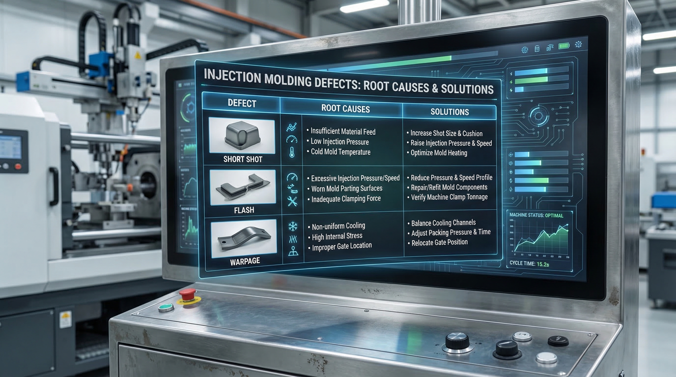
Solving injection molding defects involves a systematic analysis of machine settings, material properties, and mold design to ensure consistent part quality. You likely face the frustration of high scrap rates and delayed production cycles due to unexpected cosmetic or structural flaws. These defects don’t just waste material; they erode your profit margins and damage your reputation for precision. By implementing robust injection molding troubleshooting protocols, you can transform these production hurdles into opportunities for process optimization and improved yield.
1. How do you resolve short shots using injection molding troubleshooting?
You resolve short shots by increasing injection pressure, boosting melt temperature, or enlarging gates to ensure the cavity fills completely. Short shots occur when the plastic melt fails to reach the furthest extremities of the mold, leaving the part incomplete. Effective injection molding troubleshooting requires checking for flow restrictions like undersized runners or thin walls.
Adjusting Pressure and Melt Heat
Increasing the machine’s injection speed can help force material through narrow sections before it solidifies. But wait, there’s more to consider regarding your equipment.
- Increase injection pressure limits.
- Raise barrel temperature settings.
- Inspect the non-return valve for wear.
Examining Mold Ventilation
Insufficient venting can trap air inside the cavity, creating back-pressure that resists the incoming melt. You must ensure air escapes freely to allow the plastic to occupy every corner of the tool.
- Clean blocked ventilation channels.
- Increase the number of vent locations.
- Verify the feed throat is not obstructed.
Key Takeaway: Short shots are primarily driven by insufficient pressure or flow resistance, necessitating a check of both machine parameters and mechanical integrity.
| Potential Cause | Solution | Metric to Monitor | |
|---|---|---|---|
| Low Injection Pressure | Increase pressure settings | Peak pressure (bar) | |
| Cold Melt Temp | Raise barrel temperatures | Melt temp (°C) | |
| Poor Venting | Clean or add vents | Cycle consistency |
The data above highlights that mechanical flow and thermal energy must be perfectly balanced to avoid incomplete parts.
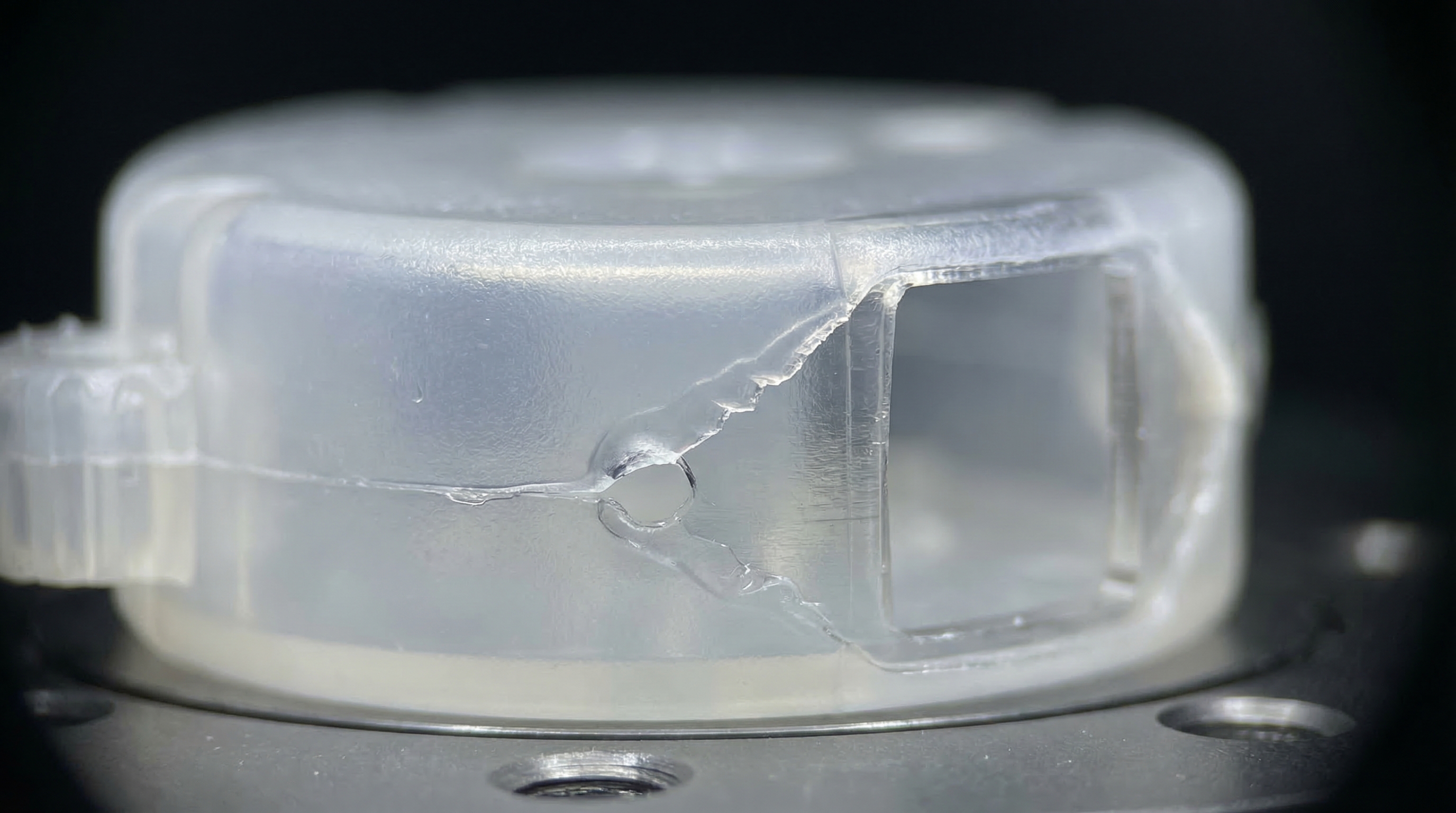
2. What steps prevent flash in injection molding troubleshooting?
You prevent flash by increasing the clamping force and reducing the injection pressure to keep the mold halves perfectly sealed. Flash appears as thin protrusions of plastic at the parting line where the material has escaped the cavity. Consistent injection molding troubleshooting ensures that your clamping tonnage always exceeds the internal cavity pressure.
Clamping Force Optimization
The clamping force must be strong enough to resist the high pressure of the injected melt. Think about this for a second before you ramp up production.
- Calculate required tonnage based on part area.
- Verify the machine’s current clamp setting.
- Reduce injection speed to lower cavity pressure.
Parting Surface Integrity
Flash often indicates a physical gap caused by worn tooling or foreign debris. But that’s not all that can go wrong with your surfaces.
- Clean the mold parting line thoroughly.
- Check for deformed mold plates or structures.
- Inspect for foreign material stuck on the tool.
Key Takeaway: Preventing flash requires a delicate balance between external clamping power and internal material viscosity.
| Potential Cause | Solution | Metric to Monitor | |
|---|---|---|---|
| Low Clamp Force | Increase clamp tonnage | Tonnage (T) | |
| High Melt Temp | Lower barrel heat | Viscosity index | |
| Worn Mold Line | Repair or resurface mold | Parting line gap |
Ensuring that your tool remains clean and your tonnage is properly calibrated will eliminate most flash occurrences.
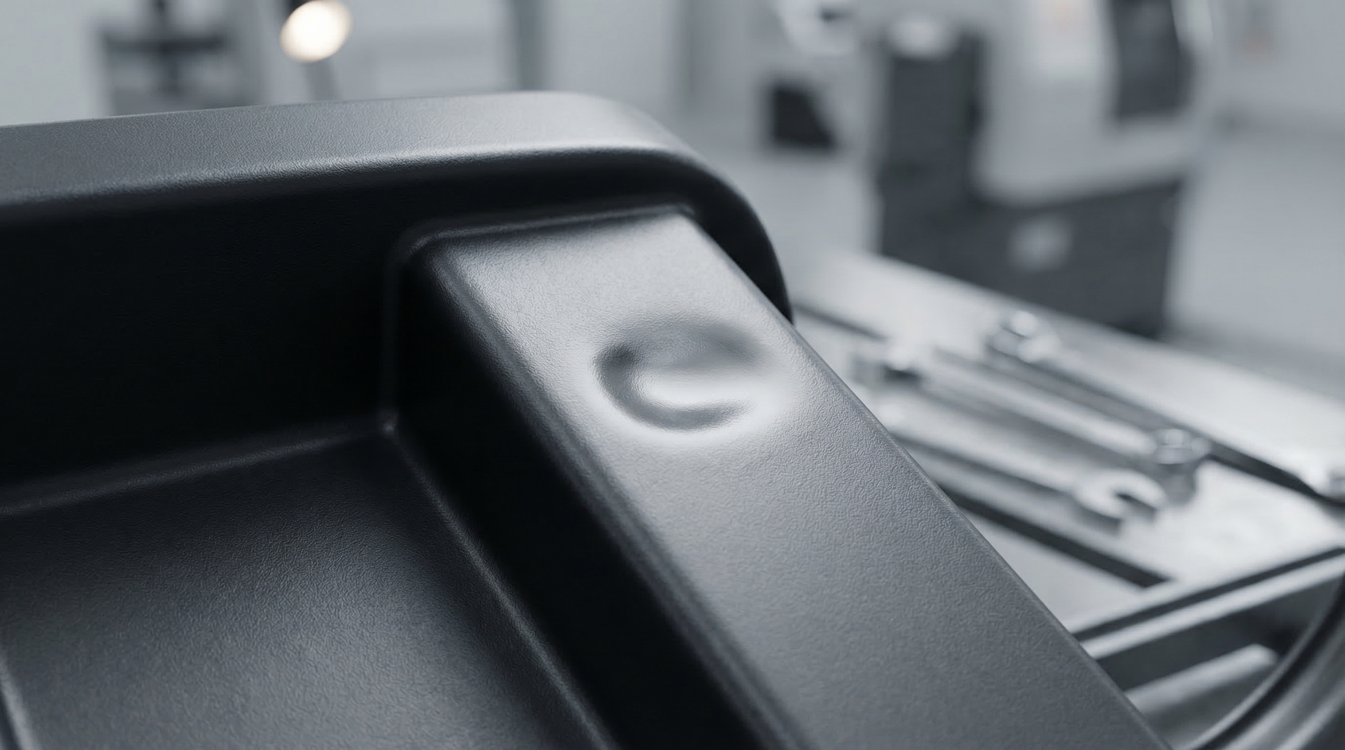
3. How can sink marks be ended with injection molding troubleshooting?
You eliminate sink marks by increasing the pack and hold pressure while extending cooling times for thick-walled sections. Sink marks are surface depressions that occur when the interior of a part shrinks away from the surface during cooling. Professional injection molding troubleshooting focuses on maintaining internal pressure until the gate is completely frozen.
Pack and Hold Control
Holding pressure must stay active until the gate solidifies to prevent material backflow. Now, consider the alternative if you ignore these settings.
- Increase packing pressure duration.
- Raise the holding pressure magnitude.
- Enlarge gates to delay gate freeze.
Cooling Cycle Adjustments
Insufficient cooling time allows the internal heat to pull the surface inward after ejection. It doesn’t stop there when dealing with thick geometries.
- Extend the overall cooling time.
- Lower the mold water temperature.
- Ensure uniform wall thickness in design.
Key Takeaway: Sink marks are the physical manifestation of internal thermal shrinkage, solved by better packing and cooling management.
| Potential Cause | Solution | Metric to Monitor | |
|---|---|---|---|
| Short Hold Time | Extend hold phase | Gate freeze time | |
| High Mold Temp | Increase cooling flow | Mold surface temp | |
| Thin Gates | Enlarge gate diameter | Flow rate (cc/s) |
A systematic approach to cooling will ensure that the part surface remains flat and aesthetically perfect.
4. Can splay marks be cured via injection molding troubleshooting?
You cure splay marks by pre-drying the plastic resin to remove moisture and reducing the screw rotation speed to minimize gas. These silver streaks are typically caused by steam or trapped volatiles within the melt during the injection cycle. Reliable injection molding troubleshooting starts with strict material handling and moisture control.
Material Preparation
The most frequent culprit for splay is residual moisture within the raw plastic pellets. But that’s not all you need to watch in the hopper.
- Dry material per manufacturer specs.
- Check desiccant dryer performance.
- Avoid mixing regrind with high moisture.
Shear Heat Reduction
High injection speeds and excessive screw RPMs generate gas due to friction and shear. Believe it or not, speed can be your enemy here.
- Reduce injection speed settings.
- Lower the back pressure slightly.
- Decrease the barrel temperature.
Key Takeaway: Splay is almost always a material or speed issue, requiring dry resin and controlled shear rates.
| Potential Cause | Solution | Metric to Monitor | |
|---|---|---|---|
| Moist Resin | Use a desiccant dryer | Dew point (°C) | |
| High Screw RPM | Reduce plasticizing speed | Screw recovery time | |
| Excessive Heat | Lower barrel profile | Melt temperature |
Eliminating moisture is the fastest way to remove the “silver streak” appearance from your high-precision parts.
5. How is warpage solved through injection molding troubleshooting?
You correct warpage by balancing the cooling rate across all part sections and ensuring the material is rigid before ejection. Warpage is the result of uneven internal stresses caused by differential cooling between different areas of the molded part. Scientific injection molding troubleshooting requires fine-tuning the mold temperature to achieve thermal equilibrium.
Cooling Channel Balance
The cooling must be consistent across both the core and cavity sides of the tool. It gets even more critical with complex geometries.
- Verify cooling water flow rates.
- Adjust core and cavity temp separately.
- Check for scale buildup in channels.
Prolonging Ejection Cycles
If a part is too soft during ejection, it will warp under the force of the pins. But wait, there’s an easy fix for this.
- Increase the cooling time.
- Reduce the melt temperature.
- Slow down the ejection speed.
Key Takeaway: Warpage is driven by internal stress, which is best managed by uniform cooling and sufficient solidification time.
| Potential Cause | Solution | Metric to Monitor | |
|---|---|---|---|
| Unbalanced Cooling | Adjust water manifold | ΔT (Temp Delta) | |
| Early Ejection | Increase cooling cycle | Part rigidity | |
| High Pack Stress | Lower packing pressure | Mold flow analysis |
By ensuring a balanced thermal environment, you can maintain the dimensional stability of even the most complex components.
6. What ends burn marks in injection molding troubleshooting?
You stop burn marks by lowering the melt temperature and improving mold venting to prevent compressed air from scorching the plastic. Burn marks often appear at the end of fill locations where air is trapped and compressed until it reaches ignition temperatures. Strategic injection molding troubleshooting involves optimizing the air evacuation process to protect material integrity.
Preventing Air Traps
Compressed air, known as “dieseling,” is the primary cause of black or rust-colored stains. Here is the kicker you need to remember.
- Clean existing mold vents.
- Add additional venting at burn sites.
- Reduce the injection speed at end-of-fill.
Controlling Melt Degradation
Excessive heat in the barrel can cause the polymer chains to break down and burn. But that’s not all that creates thermal stress.
- Lower the nozzle temperature.
- Reduce screw back pressure.
- Check the barrel for hot spots.
Key Takeaway: Burn marks are local combustion events or thermal degradation, solved by better venting and lower temperatures.
| Potential Cause | Solution | Metric to Monitor | |
|---|---|---|---|
| Trapped Air | Increase venting depth | Vent gas flow | |
| High Speed | Slow down final fill | Fill time (s) | |
| Overheating | Calibrate temp controllers | Barrel thermocouples |
Addressing these thermal issues prevents surface defects and ensures the chemical properties of your material remain intact.
7. How are voids handled by injection molding troubleshooting?
You resolve voids by increasing the packing pressure to fill internal shrinkage and ensuring the resin is properly dried. Voids are vacuum pockets that form inside the part wall when the exterior cools faster than the interior. Thorough injection molding troubleshooting focuses on forcing more material into the cavity to compensate for this thermal contraction.
Fixing Interior Shrinkage
Thick sections are most susceptible to voids as the outer skin solidifies first. You might be wondering why this happens so often.
- Increase pack and hold pressures.
- Extend the holding time duration.
- Lower the melt temperature.
Gas Evacuation Techniques
Unlike voids, bubbles are caused by trapped gas or moisture that hasn’t been evacuated. Let’s look at the best ways to stop this.
- Increase the back pressure.
- Verify the resin drying cycle.
- Slow the injection speed.
Key Takeaway: Voids are vacuum-driven gaps while bubbles are gas-driven; both require better packing and material prep.
| Potential Cause | Solution | Metric to Monitor | |
|---|---|---|---|
| Low Pack Pressure | Increase packing force | Cushion size (mm) | |
| High Melt Temp | Lower the heat profile | Cooling rate | |
| Thick Sections | Redesign for thin walls | Wall thickness |
Ensuring a consistent material cushion during the holding phase is the most effective way to prevent internal voids.
8. What stops jetting during injection molding troubleshooting?
You minimize jetting by placing gates against metal surfaces to break the flow and reducing the initial injection speed. Jetting occurs when the melt sprays into the cavity like a snake, rather than flowing in a uniform wave front. Advanced injection molding troubleshooting often requires adjusting the gate geometry to promote impingement.
Strategic Gate Placement
The material should hit a wall or pin immediately after entering the cavity to disperse the energy. Let’s dig deeper into the physics of this flow.
- Relocate gates to favor impingement.
- Use overlap or submarine gates.
- Increase the gate cross-section.
Velocity Profile Tuning
A slow initial injection speed prevents the “shooting” effect associated with narrow gates. But that’s just the beginning of the solution.
- Use a profiled injection speed.
- Increase the melt temperature.
- Raise the mold temperature.
Key Takeaway: Jetting is a flow-pattern failure solved by breaking the melt stream or slowing its entry velocity.
| Potential Cause | Solution | Metric to Monitor | |
|---|---|---|---|
| High Velocity | Reduce initial speed | Injection profile | |
| Poor Gate Spot | Relocate for impingement | Flow simulation | |
| Cold Material | Increase nozzle heat | Melt viscosity |
Correcting the flow pattern at the start of the cycle will eliminate the unsightly “worm” marks on your part surface.
9. How do weld lines vanish with injection molding troubleshooting?
You manage weld lines by increasing the melt and mold temperatures so that converging flow fronts fuse together seamlessly. Weld lines are visible seams where two or more material flows meet during the filling process. In many cases, injection molding troubleshooting involves speeding up the injection to ensure the flows meet while still hot.
Thermal Fusion Optimization
The two fronts must be molten enough to intermingle their polymer chains. Believe it or not, temperature is your best tool here.
- Raise the barrel temperature.
- Increase mold surface temperature.
- Insulate the mold plates.
Enhancing Mold Ventilation
Air trapped at the meeting point of two flows prevents them from bonding correctly. But wait, there is a venting trick you should know.
- Add vents at the weld line site.
- Increase the injection speed.
- Adjust gate locations to move the line.
Key Takeaway: Weld lines are fusion failures that require more heat, higher speed, and better air evacuation to resolve.
| Potential Cause | Solution | Metric to Monitor | |
|---|---|---|---|
| Cold Flow Fronts | Increase melt/mold heat | Weld line strength | |
| Slow Injection | Boost fill speed | Fill time | |
| Trapped Air | Add vents at meeting point | Visual seam depth |
By improving the thermal energy at the point of contact, you can make weld lines nearly invisible and structurally sound.
10. How does injection molding troubleshooting resolve gate vestige?
You reduce gate vestige by optimizing the holding pressure timing and ensuring the gate geometry allows for a clean break. Gate vestige is the leftover material at the entry point that can interfere with part assembly or aesthetics. Effective injection molding troubleshooting requires a balance between gate freeze and ejection timing.
Pressure Profiling
The transition from injection to holding pressure must be timed to avoid over-packing the gate. That’s just the beginning of the adjustment process.
- Lower the hold pressure.
- Reduce the hold time duration.
- Adjust the decompression (suck-back).
Gate Design Refinement
The physical shape of the gate determines how easily it shears off during ejection. But there is more to consider regarding tool maintenance.
- Sharpen the gate edges.
- Use a smaller gate orifice.
- Switch to a self-shearing gate type.
Key Takeaway: Gate vestige is a mechanical separation issue solved by pressure timing and gate geometry refinement.
| Potential Cause | Solution | Metric to Monitor | |
|---|---|---|---|
| Over-packing | Lower hold pressure | Part weight (g) | |
| Dull Gate | Sharpen or replace insert | Vestige height (mm) | |
| High Melt Temp | Lower nozzle temperature | Stringing tendency |
Refining the gate area ensures that every part comes off the machine ready for assembly with no secondary trimming required.
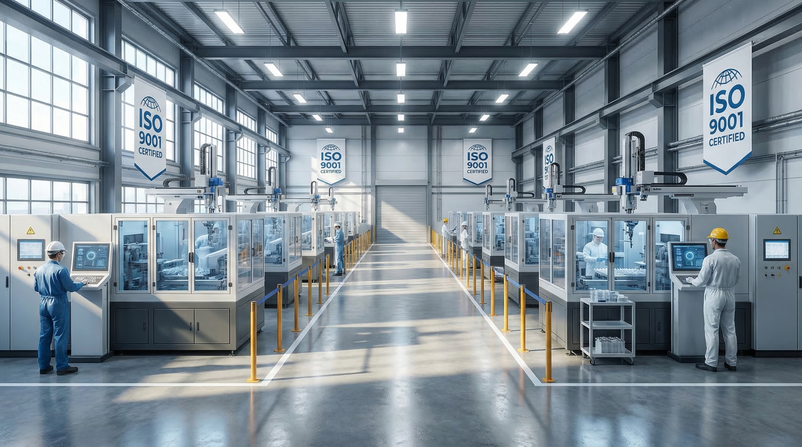
Summary and Recommendations
Troubleshooting injection molding defects requires a systematic approach that balances material preparation, machine settings, and mold engineering. By isolating variables like temperature, pressure, and timing, you can significantly reduce scrap and improve the structural integrity of your parts. CN Precision Manufacturing is dedicated to delivering flawless components through rigorous DFM analysis and ISO-certified quality controls. Our mission is to partner with global leaders to solve the most complex manufacturing challenges with precision and reliability. To eliminate production hurdles in your next project, contact us today .
Frequently Asked Questions
Can I fix splay marks without a desiccant dryer?No, because ambient air drying is rarely sufficient for hygroscopic materials like Nylon or PC. You must use a professional dryer to achieve the moisture levels required for a defect-free surface.
What’s the best way to determine if a void is a vacuum or a gas bubble?Heating the part with a heat gun is the most reliable method. If the defect expands and becomes a bubble, it is trapped gas; if it remains a depression or collapses further, it is a vacuum void.
How do I know if my clamping force is too low?Directly check for flash appearing only during the high-pressure injection phase. If the parting line opens even slightly when the peak pressure is reached, your machine needs more tonnage or lower injection speed.
Can I move a weld line without changing the mold design?Yes, by adjusting the injection speed or changing the melt temperature. These changes alter the flow velocity of different branches, causing them to meet at a different physical location in the cavity.
What’s the best injection speed for preventing burn marks?Usually a lower speed is best, specifically a “profiled” injection that slows down just before the material reaches the end of the fill. This allows trapped air more time to escape through the vents without overheating.