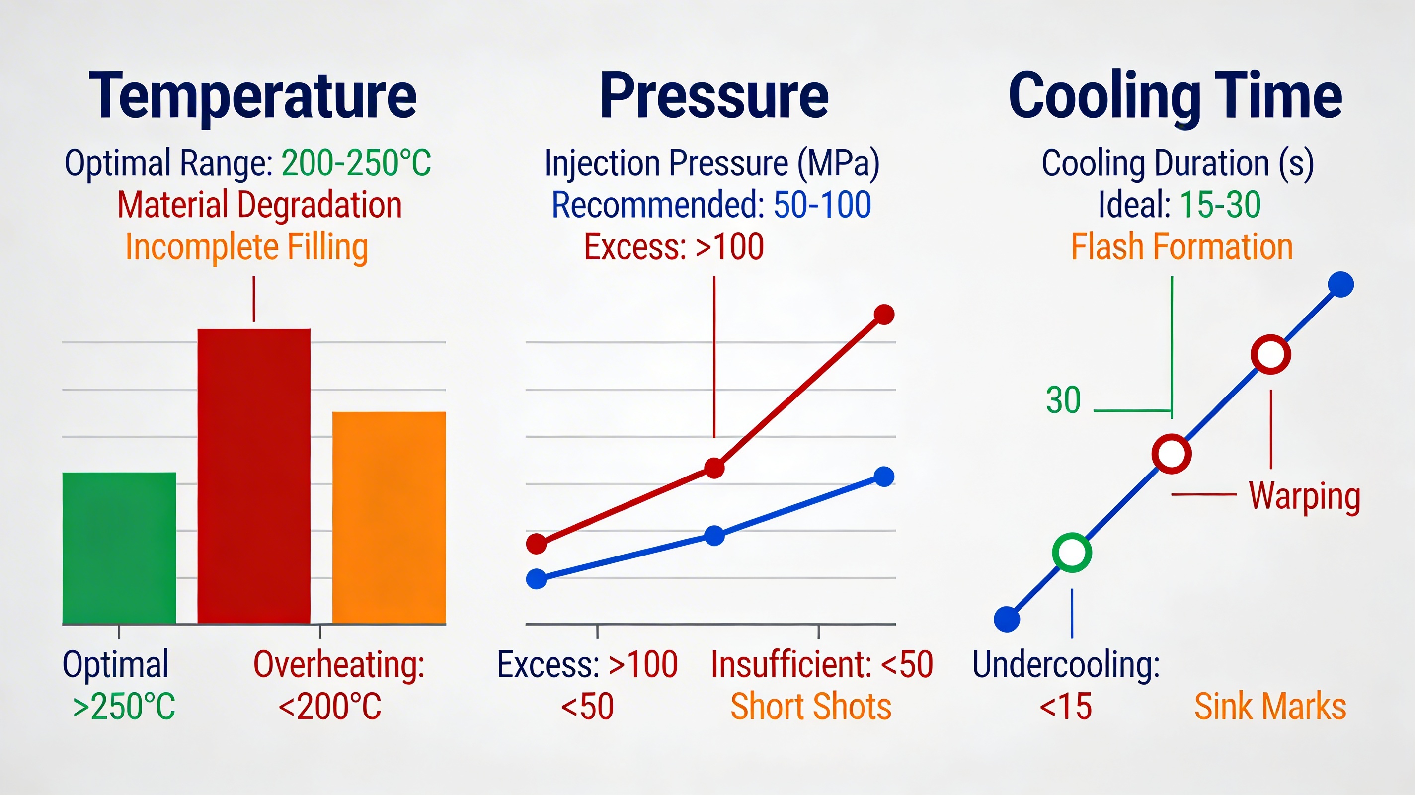
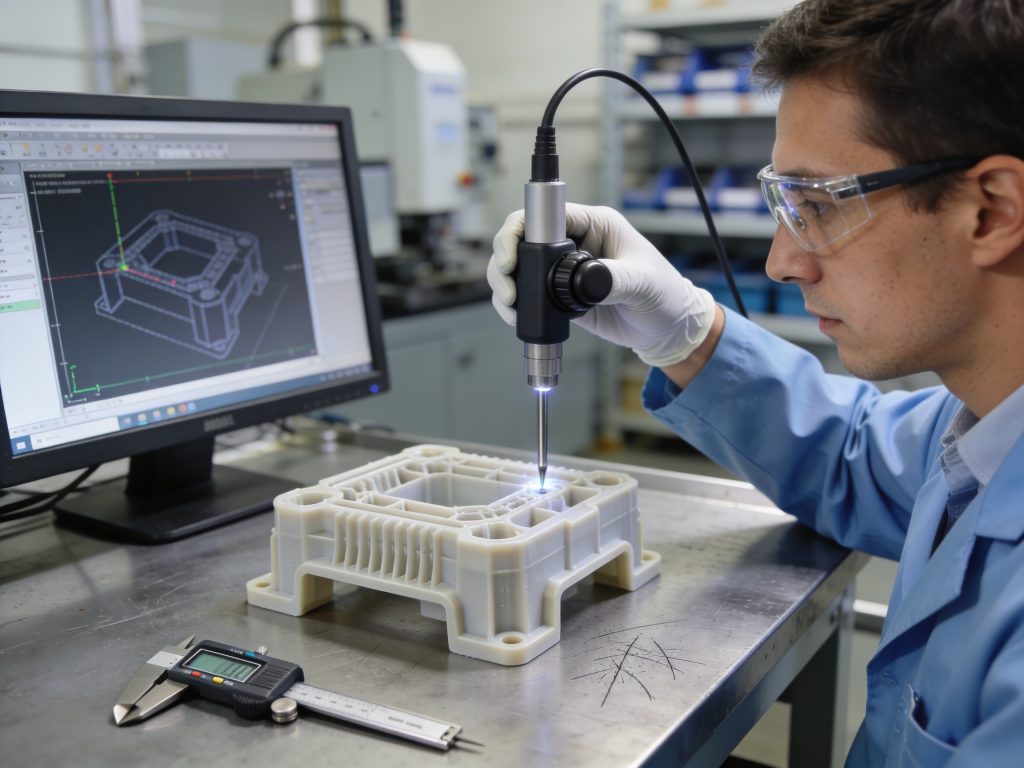
Identifying and mitigating common injection molding defects requires a balance of thermal control, material science, and precise tool design to maintain high yield rates. Manufacturers often struggle with unpredictable surface flaws or structural failures that lead to high scrap rates and wasted resources. These issues can delay your production timelines and cause significant financial losses if the root causes are not diagnosed and resolved early in the cycle. By mastering the variables that cause injection molding defects , you can optimize your machine settings and engineering designs to ensure consistent, high-quality plastic components.
How can flow lines be prevented as injection molding defects?
Flow lines are prevented by increasing injection speed and pressure to ensure the molten resin fills the mold cavity uniformly before it begins to solidify. These wavy patterns often signify that the material is cooling at different rates, which is a common issue when managing injection molding defects in high-aesthetic parts.
Adjusting injection speed and pressure
Low injection speeds cause the plastic to cool prematurely, creating visible streaks on the surface. You must calibrate your machine to maintain a steady flow that reaches the extremities of the mold without losing temperature.
Consider this:
- Increase pressure to force resin into tight corners.
- Monitor nozzle temperature to maintain ideal viscosity.
- Use flow simulations to predict material behavior.
Refining gate location and design
Strategic gate placement helps avoid abrupt changes in flow direction that trigger turbulence. Moving the gate to a thicker section of the part often reduces the occurrence of these visual imperfections.
Key Takeaway: Correcting flow lines involves balancing the speed of the fill with the thermal stability of the resin to prevent premature cooling.
| Factor | Solution | Impact | |
|---|---|---|---|
| Injection Speed | Increase | Prevents premature solidification | |
| Gate Position | Relocate to thick areas | Smoothens material flow | |
| Pressure | Optimize | Ensures uniform cavity filling |
Effective pressure management is only the first step in stabilizing your production line.
Why do sink marks occur among common injection molding defects?
Sink marks appear as depressions in thick sections of a part because the inner core cools and shrinks slower than the outer surface. When dealing with various injection molding defects, sink marks are particularly frustrating as they compromise both the visual quality and the dimensional accuracy of your product.
Increasing holding pressure and time
Applying higher holding pressure forces more material into the cavity during the cooling phase to compensate for shrinkage. You must ensure the gate does not freeze off too early, or the extra pressure will not reach the affected area.
But wait, there is more:
- Extend cooling cycles for thicker walls.
- Reduce the melt temperature to limit total shrinkage.
- Ensure consistent wall thickness throughout the design.
Optimizing rib-to-wall thickness ratios
Designing ribs that are no more than 60% of the main wall thickness prevents localized heat concentration. This engineering rule is vital for preventing the “pulling” effect that creates surface dents.
Key Takeaway: Sink marks are mitigated by ensuring that the part cools evenly and that sufficient pack pressure is maintained throughout the solidification process.
| Factor | Solution | Impact | |
|---|---|---|---|
| Holding Pressure | Increase | Compels more material into shrinks | |
| Cooling Time | Extend | Allows core to stabilize | |
| Rib Design | 60% ratio rule | Minimizes thermal mass |
While surface depressions are visible, internal issues can be even more detrimental to your part’s performance.
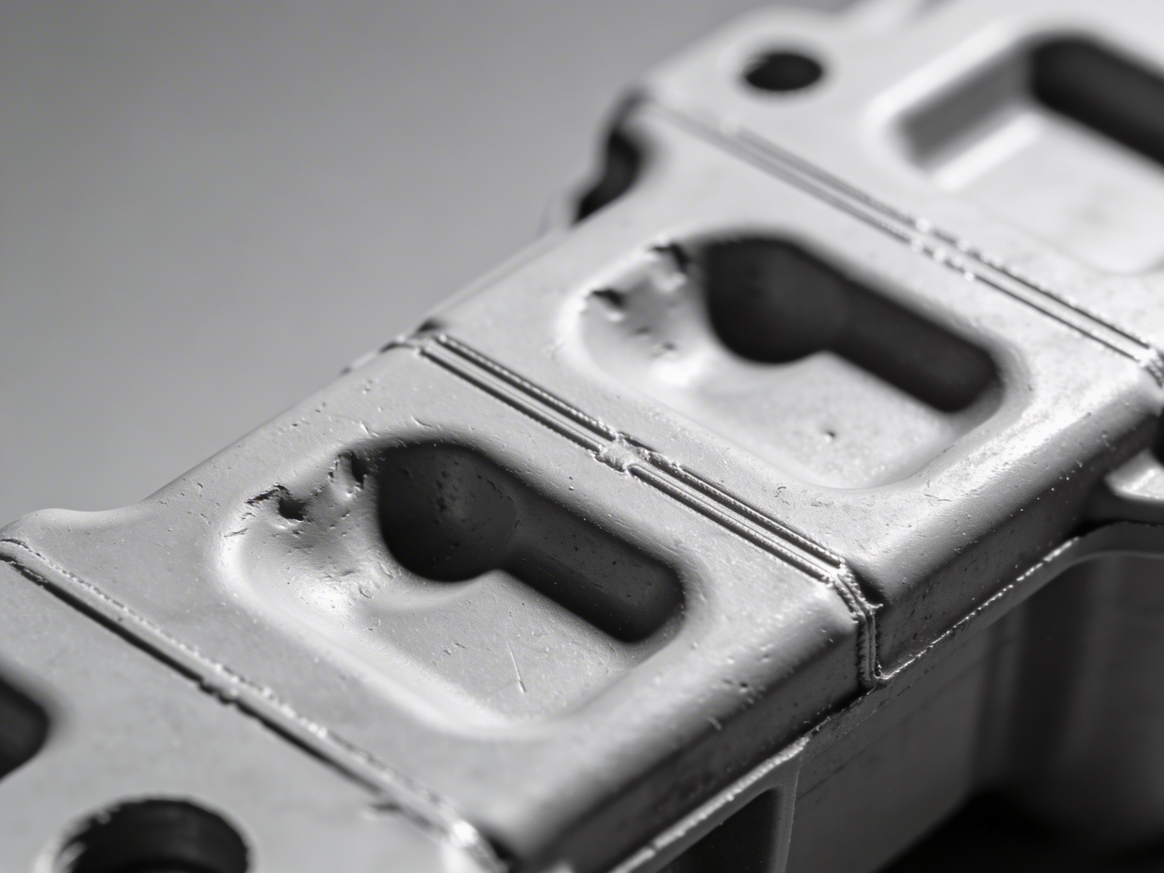
Can vacuum voids be eliminated as injection molding defects?
Vacuum voids can be eliminated by increasing the packing pressure and slowing the cooling rate to prevent air pockets from forming within the part’s core. Unlike other injection molding defects , these internal holes are often invisible to the naked eye but can lead to structural failure under stress.
Controlling cooling rates at the core
If the outer skin hardens too quickly while the center remains molten, the resulting internal tension pulls the material apart. You should adjust your mold temperature to ensure a more gradual thermal gradient between the surface and the center.
Here is the deal:
- Use localized cooling channels for thick areas.
- Switch to materials with lower shrinkage rates.
- Monitor moisture levels in hygroscopic resins.
Enhancing pack pressure during solidification
Maintaining physical density within the mold cavity is the best defense against gas-related void formation. High packing pressure ensures the molten plastic occupies every micron of space as it turns from liquid to solid.
Key Takeaway: Eliminating vacuum voids requires a combination of high pack pressure and controlled cooling to keep the material dense and uniform.
| Factor | Solution | Impact | |
|---|---|---|---|
| Core Cooling | Slow down | Reduces internal stress | |
| Pack Pressure | Maximize | Fills potential internal gaps | |
| Material Choice | Low-shrinkage grades | Prevents molecular separation |
Once you have secured the internal structure, you must address the integrity of the surface layers.
What causes delamination in plastic injection molding defects?
Surface delamination is primarily caused by material contamination or moisture that prevents the polymer layers from bonding correctly during the injection cycle. This is one of the more severe injection molding defects because the part’s surface can peel off like thin flakes, making it unusable for functional or aesthetic applications.
Eliminating moisture and contaminants
Even a small amount of water vapor trapped in the resin can turn into steam, creating faults between the material layers. You must use desiccant dryers to ensure your material is completely dry before it enters the hopper.
Consider this:
- Avoid excessive use of mold release agents.
- Verify the compatibility of different resin batches.
- Limit the ratio of regrind material used in production.
Reducing shear stress via gate redesign
High shear rates can “tear” the polymer melt as it enters the cavity, leading to separation. Redesigning gates to be larger or using fan gates can help distribute the material more gently.
Key Takeaway: Preventing delamination is a matter of material purity and managing the physical stress applied to the melt during the fill.
| Factor | Solution | Impact | |
|---|---|---|---|
| Drying | Use desiccant dryers | Removes destructive moisture | |
| Contamination | Strict QC | Ensures molecular bonding | |
| Shear Stress | Increase gate size | Prevents material tearing |
Structural integrity is also threatened when two separate flows of plastic fail to merge seamlessly.
Are weld lines inevitable among injection molding defects?
Weld lines are not inevitable and can be minimized by raising the mold temperature and increasing the injection speed to ensure flow fronts bond effectively. These lines occur where two paths of molten plastic meet, and they are common injection molding defects that create both visual flaws and mechanical weak points.
Raising melt and mold temperatures
When the material is hotter at the point of collision, the polymer chains can intermingle more easily. This “knitting” effect is crucial for restoring the strength of the part at the junction point.
But wait, there is more:
- Increase injection speed to hit the junction faster.
- Move gates to relocate weld lines to hidden areas.
- Use resins with lower viscosity to improve flow.
Strategic gate positioning
By changing where the resin enters the mold, you can control exactly where the flow fronts meet. You should aim to place these junctions in areas that do not experience high mechanical stress or are not visible to the end user.
Key Takeaway: You can solve weld line issues by ensuring the material remains sufficiently fluid to merge into a single, cohesive structure upon contact.
| Factor | Solution | Impact | |
|---|---|---|---|
| Temperature | Increase melt/mold heat | Promotes molecular knitting | |
| Injection Speed | Accelerate | Reduces cooling before contact | |
| Design | Relocate knit lines | Protects structural integrity |
Even with perfect bonding, a project can fail if the material doesn’t reach the ends of the mold.
How do short shots happen in common injection molding defects?
Short shots occur when the molten plastic fails to fill the entire mold cavity, usually due to flow restrictions, insufficient pressure, or trapped air. In the world of injection molding defects, a short shot results in an incomplete part that must be scrapped immediately, increasing your production costs.

Machine capacity and air vent optimization
If your machine’s shot size is too small for the mold, you will never achieve a full part. Additionally, if air cannot escape the cavity through vents, it creates an “air lock” that blocks the incoming plastic.
Here is the deal:
- Clean vents regularly to prevent gas buildup.
- Increase the injection pressure to overcome resistance.
- Verify that gates are not blocked or too narrow.
Managing resin viscosity and flow
Materials with high viscosity may struggle to fill thin-walled sections of a complex mold. Increasing the melt temperature reduces this resistance, allowing the plastic to flow further into the tool.
Key Takeaway: Solving short shots requires a check of both machine capability and the physical path the plastic takes through the mold.
| Factor | Solution | Impact | |
|---|---|---|---|
| Venting | Add or clean vents | Eliminates air resistance | |
| Shot Size | Calibrate to mold | Ensures sufficient material | |
| Temperature | Increase | Decreases flow resistance |
While filling the mold is critical, the way the part cools determines its final shape and usability.
Why is warping so common in injection molding defects?
Warping is common because it results from non-uniform shrinkage during the cooling process, often caused by inconsistent temperatures within the mold. This is one of the most difficult injection molding defects to solve because it involves the complex relationship between part geometry and thermal balance.
Achieving thermal balance in cooling circuits
If one side of the mold is hotter than the other, the part will bend toward the side that cools more slowly. You must ensure your cooling lines are clean and that the coolant flow is consistent across all sections of the tool.
Consider this:
- Use symmetric mold designs whenever possible.
- Switch to amorphous resins, which shrink less than crystalline ones.
- Adjust the hold time to allow the part to set fully.
Material grade and filler impacts
Adding glass fibers or other fillers can change how a part shrinks. While fillers can add strength, they often introduce anisotropic shrinkage, which increases the likelihood of the part twisting out of shape.
Key Takeaway: Warping is prevented by maintaining a uniform cooling rate across the entire part to minimize internal stresses.
| Factor | Solution | Impact | |
|---|---|---|---|
| Cooling Balance | Equalize temperatures | Prevents uneven bending | |
| Material | Amorphous resins | Offers more stable shrinkage | |
| Hold Time | Extend | Fixes the shape before ejection |
Sometimes, the heat required to prevent warping can lead to another type of surface damage.
What causes burn marks to appear as injection molding defects?
Burn marks are caused by trapped air that becomes overheated through compression, known as the “diesel effect,” or by material degradation from excessive heat. These dark discolorations are persistent injection molding defects that ruin the appearance of the part and can even damage the surface of your expensive tooling.
Improving mold venting systems
When air is trapped in a pocket and compressed by the incoming plastic, it can reach temperatures high enough to char the resin. You should add deep, wide vents at the end of the flow paths to allow air to escape freely.
But wait, there is more:
- Reduce injection speeds to lower friction.
- Clean the mold surface of gas residues and “plate-out.”
- Decrease the melt temperature if degradation is the cause.
Regular maintenance and cleaning
Gases released by certain resins can leave deposits on the mold that eventually burn. A strict maintenance schedule ensures these residues are removed before they cause defects in your production run.
Key Takeaway: Preventing burn marks is about managing the air inside the mold and the speed at which you displace it with plastic.
| Factor | Solution | Impact | |
|---|---|---|---|
| Venting | Enhance end-of-fill vents | Prevents compressed air ignition | |
| Speed | Lower injection velocity | Reduces shear and friction heat | |
| Cleaning | Periodic mold wipes | Removes carbonized residues |
Managing speed is also the key to preventing “snake-like” patterns from forming on your parts.
How can jetting be prevented among injection molding defects?
Jetting is prevented by ensuring the initial flow of plastic makes contact with a mold wall immediately upon entering the cavity. This “snake-like” pattern occurs when a high-velocity stream of resin enters a large area and cools before the rest of the cavity fills, making it a visible and structural flaw in many injection molding defects scenarios.
Gate design and impingement
By placing the gate so the plastic hits a pin or a wall, you break the momentum of the “jet.” This causes the plastic to fill the cavity in a more gradual, expanding manner rather than a chaotic stream.
Here is the deal:
- Use fan or tab gates to spread the flow.
- Profile your injection speed to start slowly.
- Increase the melt temperature to improve fusion.
Regulating initial flow velocity
Modern machines allow you to slow down the fill specifically during the initial stage when the plastic enters the gate. This prevents the “shotgun” effect that leads to jetting in thick-walled parts.
Key Takeaway: Jetting is a physics problem that you can solve by redirecting the material flow to promote a steady, laminar fill.
| Factor | Solution | Impact | |
|---|---|---|---|
| Gate Placement | Aim at a wall | Breaks flow momentum | |
| Fill Profile | Start slow | Ensures controlled entry | |
| Gate Type | Use tab/fan gates | Widens the entry stream |
Finally, if you apply too much pressure to solve these fill issues, you might run into the problem of excess material.
Why does flash occur in common injection molding defects?
Flash occurs when the injection pressure exceeds the clamp force of the machine, or when the mold halves do not fit together perfectly, allowing molten plastic to leak out. Among the most common injection molding defects, flash requires manual trimming and labor, which significantly lowers your manufacturing efficiency.
Clamp force and machine sizing
You must ensure that the machine’s tonnage is sufficient to hold the mold shut against the high pressure of the plastic. If you are using a machine that is too small for the part’s projected area, flash is almost inevitable.
Consider this:
- Repair worn or damaged parting lines on the tool.
- Lower the injection pressure if the mold is over-packing.
- Increase the material viscosity to reduce leakage.
Tooling maintenance and integrity
Over time, the edges of a mold can wear down, creating small gaps at the parting line. Regular inspection and precision machining are necessary to keep the seal tight and prevent material from escaping.
Key Takeaway: Preventing flash requires a perfect match between your machine’s clamping power and the structural integrity of your mold.
| Factor | Solution | Impact | |
|---|---|---|---|
| Clamp Force | Increase tonnage | Holds mold shut under pressure | |
| Parting Line | Repair/Regrind | Ensures a tight physical seal | |
| Pressure | Reduce pack/hold | Prevents over-filling of the tool |
By mastering these ten areas, you can significantly reduce scrap and improve the overall quality of your manufacturing output.
Conclusion
Understanding and preventing injection molding defects is the key to maintaining a profitable and efficient B2B manufacturing operation. We have explored how to solve issues ranging from aesthetic flow lines and sink marks to structural weld lines and vacuum voids. By optimizing your machine settings, refining your mold designs, and maintaining material purity, you can eliminate the costly scrap and delays that hinder your growth.
Our team is dedicated to helping you achieve zero-defect production through expert DFM analysis and precision engineering. If you are ready to enhance your product quality and optimize your manufacturing costs, contact us today to discuss your next project. We believe that every high-performance part starts with a proactive approach to risk management and technical excellence.
FAQ Section
Can I fix injection molding defects without modifying the mold?
Yes, many defects like flow lines, sink marks, and short shots can be resolved by adjusting machine parameters such as temperature, pressure, and injection speed. However, issues rooted in gate placement or wall thickness will eventually require tooling modifications for a permanent fix.
What is the best way to monitor moisture in resin?
The most reliable method is using a moisture analyzer in conjunction with high-quality desiccant dryers. Simply checking the drying time is often insufficient for hygroscopic materials like Nylon or Polycarbonate that absorb moisture rapidly.
Are certain materials more prone to warping?
Yes, semi-crystalline resins like PBT and PE are generally more prone to warping because they have higher and more localized shrinkage rates compared to amorphous resins like ABS or PC. Proper cooling circuit design is critical when working with these materials.
How do I know if my injection speed is too high?
If you begin to see burn marks, jetting, or flash, your injection speed is likely too high. High speeds create excessive shear heat and can overwhelm the venting capacity of the mold, leading to these specific flaws.
How often should I inspect my mold for flash prevention?
You should conduct a visual inspection of the parting lines every shift and perform a deep maintenance check based on cycle counts, typically every 50,000 to 100,000 cycles. Preventing flash is far more cost-effective than repairing damaged tool steel.