The basics of injection molding design involve optimizing part geometry, cooling rates, and material flow to ensure structural integrity and manufacturing efficiency. You often face the pressure of launching products quickly, but ignoring technical constraints leads to warped components and expensive rework. Mastering a professional injection mold design allows you to minimize stresses and achieve high-precision results for global manufacturing.
Why is wall thickness vital in injection mold design?
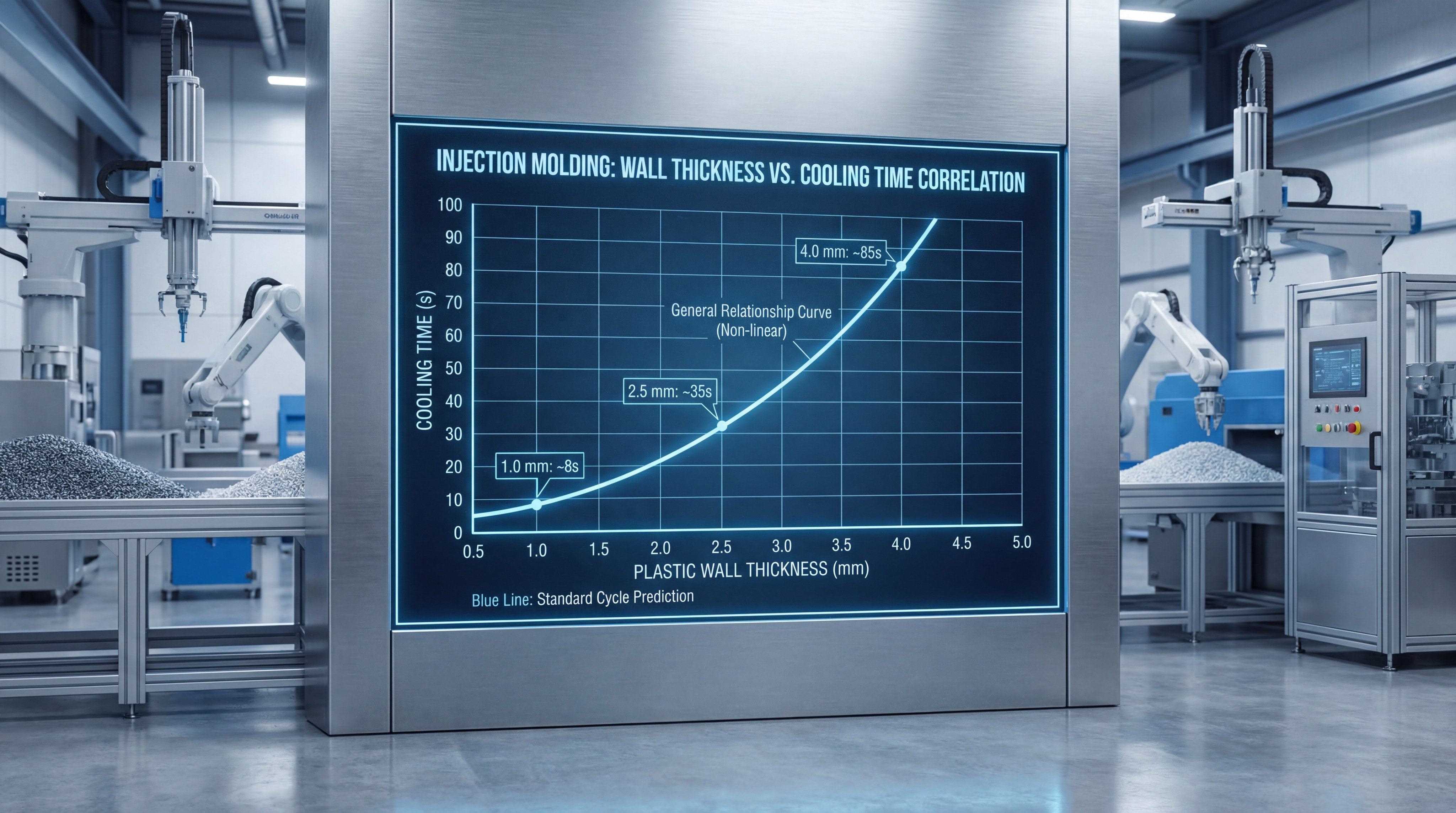
Maintaining a specific wall thickness is the primary factor in a successful injection mold design because it directly dictates how quickly and evenly your part cools. If your walls are inconsistent, the material will shrink at different rates, leading to internal stress and catastrophic warping. You should aim for a range between 2mm and 4mm for most standard plastic resins to balance strength and cycle time.
Selecting optimal thickness ranges
You must evaluate the specific flow properties of your chosen resin when setting nominal wall dimensions. Different materials have varying viscosities that determine how easily they fill thin cavities during the production cycle.
Think about this:
- ABS: 1.1mm – 3.5mm
- Polypropylene: 0.6mm – 3.8mm
- Polycarbonate: 1.0mm – 3.8mm
- Nylon: 0.7mm – 3.0mm
The necessity of uniform walls
Uniformity ensures that the entire part reaches a solid state simultaneously, preventing the thicker sections from pulling on the thinner ones. If you must change thickness, ensure the transition is gradual to prevent flow turbulence and aesthetic defects.
| Parameter | Standard Range | Primary Benefit | |
|---|---|---|---|
| Wall Thickness | 2.0mm – 4.0mm | Minimizes cooling time and prevents voids. | |
| Thickness Variance | Max 10% | Ensures dimensional stability and avoids warp. | |
| Transition Ratio | 3-to-1 | Provides smooth material flow during injection. |
This data confirms that strict adherence to thickness limits eliminates the majority of common manufacturing defects before they occur.
Key Takeaway: Consistent wall thickness is the foundation of part quality, directly affecting everything from total production cost to the functional lifespan of the component.
How does draft angle affect your injection mold design?
Applying a draft angle is essential for your injection mold design to ensure that the finished part can be ejected from the tool without damage. Without this taper, the cooling plastic will grip the mold surfaces tightly, causing friction that leads to drag marks or part breakage. You should incorporate at least one degree of draft for every inch of depth to facilitate a clean release.
Minimum release angle requirements
For most applications, a minimum of 1.0 to 1.5 degrees of draft is considered the industry standard for smooth surfaces. This small angle creates an immediate gap as the part moves, allowing the ejection pins to function without excessive force.
You see:
- Draft prevents vacuum formation during mold opening.
- It reduces wear and tear on the precision tool steel.
- Internal ribs require higher draft than external walls.
- Deep parts benefit from 3.0 degrees or more for safety.
Adjusting draft for textured finishes
If your design includes a matte or grained texture, you must increase the draft angle significantly to prevent the peaks of the texture from scuffing. Texture creates microscopic undercuts that will scrape against the mold unless there is sufficient clearance provided by the taper.
| Surface Type | Recommended Draft | Rationale | |
|---|---|---|---|
| Polished Finish | 1.0° | Basic mechanical release with minimal friction. | |
| Light Texture | 3.0° | Accounts for surface depth and avoids scuffing. | |
| Heavy Grain | 5.0° – 7.0° | Prevents the texture from dragging during ejection. |
The correlation between surface complexity and draft angle proves that aesthetic choices have a direct impact on the mechanical layout of the mold.
Key Takeaway: Draft is not an optional feature but a mechanical requirement that protects both the aesthetic finish of your part and the longevity of the expensive production tool.
Can ribs improve the strength of injection mold design?
You can increase the stiffness of your part without adding bulk by incorporating ribs into your injection mold design . These features allow you to maintain thin, fast-cooling walls while providing the structural rigidity required for demanding industrial applications. Properly designed ribs provide the necessary reinforcement while saving on material costs and reducing overall part weight.
Strategic rib placement and height
Ribs should be placed in areas that experience the most mechanical load, such as long spans or mounting points. You must ensure the height of the rib does not exceed three times the nominal wall thickness to avoid filling issues.
Here is the deal:
- Rib thickness should be 50% to 60% of the wall.
- Rib height should be maximum 3x the wall thickness.
- Spacing should be at least 2x the wall thickness.
- Base radii are needed for stress distribution.
Designing bosses for assembly
Bosses serve as the mounting points for screws or inserts and must be designed with external support ribs for maximum stability. If a boss is too thick at its base, it will create a visible sink mark on the exterior of the product.
| Feature | Design Ratio | Goal | |
|---|---|---|---|
| Rib Thickness | 0.5 x Wall | Avoids sink marks on the show surface. | |
| Rib Height | 3.0 x Wall | Prevents material from freezing prematurely. | |
| Boss Diameter | 2.0 x Hole Size | Provides sufficient material for fastener grip. |
Analytical review of these geometric ratios shows that structural enhancements must be carefully balanced against the cosmetic requirements of the final component.
Key Takeaway: Using thin ribs instead of solid blocks provides the highest strength-to-weight ratio while maintaining the fast cooling cycles required for profitable high-volume production.
Where should you place gates for injection mold design?
The gate serves as the entry point for molten plastic and is a pivotal element of injection mold design because it determines the flow pattern and stress distribution. You must carefully place the gate to ensure the cavity fills evenly and the pressure is distributed across the part geometry. Poor gate location leads to unsightly flow marks, weak weld lines, and dimensional inaccuracies that compromise the assembly.
Selecting between gate types
You have several options when choosing a gate, including edge gates for simple flat parts and sub-gates for automatic degating. Your choice depends on whether you can tolerate a visible vestige or if you require a completely clean cosmetic surface.
It gets better:
- Edge gates are easy to machine but leave a scar.
- Sub-gates (tunnel gates) automatically separate during ejection.
- Hot tip gates leave a tiny nub and eliminate runner waste.
- Direct gates are used for large cylindrical parts.
Optimizing flow and packing
You should always gate into the thickest section of the part to ensure the material can pack properly as it cools from the inside out. If you gate into a thin section, the gate will freeze early, leaving the thicker areas under-packed and prone to shrinking inward.
| Gate Category | Typical Application | Labor Requirement | |
|---|---|---|---|
| Manual Trim | Low-volume or bulky parts | Requires operator to cut part from runner. | |
| Automatic Trim | High-volume production | Shears part from runner during mold open. | |
| Hot Runner | Zero-waste production | No runner removal; highly automated. |
Determining the appropriate gate type early in the design phase can reduce secondary labor costs by up to 100% while improving cycle consistency.
Key Takeaway: Proper gate placement balances the need for structural packing with the requirement for minimal cosmetic interference on the final visible surfaces.
How to avoid sink marks during injection mold design?
Sink marks are depressions on the surface of a part caused by localized thick sections, and they are avoided in injection mold design by maintaining strict thickness ratios. You must realize that when a feature like a rib or boss is too thick at its base, the excess heat causes that specific area to shrink more than the surrounding wall. Adhering to professional design standards prevents these unsightly craters from ruining your product’s cosmetic finish.
Applying the 60 percent rule
To prevent sink, the thickness of a rib at its base should never exceed 60% of the thickness of the nominal wall it is attached to. This ensures the rib cools faster than the main wall, preventing it from pulling the wall inward during the solidification phase.
But wait, there’s more:
- Reduce the ratio to 40% for high-shrink materials.
- Coring out solid sections creates hollow, uniform features.
- Added texture can help hide minor cosmetic sink marks.
- Increased packing pressure can sometimes mitigate sink.
Utilizing coring techniques
If your design requires a thick section for structural reasons, you should core it out to create a hollowed-out feature with uniform walls. This technique keeps the exterior dimensions identical while removing the problematic mass of plastic that causes thermal delay.
| Mitigation Method | Primary Action | Cosmetic Effect | |
|---|---|---|---|
| Coring | Removes internal mass | Eliminates depression and reduces weight. | |
| Rib Reduction | Limits base thickness | Prevents pulling on the nominal wall. | |
| Material Choice | Lower shrink resin | Provides better dimensional stability. |
Analysis of cooling rates demonstrates that adhering to thickness ratios eliminates surface depressions by ensuring simultaneous solidification across the part.
Key Takeaway: Managing the intersection of features is the only way to ensure a perfectly flat exterior surface, which is critical for premium brand perception.
What materials are best for your injection mold design?
Every resin has a unique shrink rate that must be factored into your injection mold design to ensure the final part meets its dimensional specifications. You cannot design a part for one material and then switch to another without potentially changing the mold’s dimensions or the part’s performance profile. Your choice of plastic dictates everything from the required draft angle to the strength of the finished component.
Understanding material shrink rates
Plastic shrinks as it cools, and different materials move at vastly different rates, typically ranging from 0.001 to 0.060 inches per inch. Your mold must be machined slightly larger than the final part to compensate for this inevitable movement during the cooling process.
As it turns out:
- Amorphous resins (ABS, PC) shrink very little.
- Crystalline resins (PP, PE) shrink significantly.
- Glass-filled resins have high dimensional stability.
- Additives can change the flow and shrink properties.
Comparing amorphous and crystalline resins
Amorphous resins are generally easier to mold into tight tolerances because they shrink uniformly in all directions. Crystalline resins offer better chemical resistance and durability but are much more prone to warping and shrinking if the cooling is not perfectly managed.
| Resin Class | Common Examples | Typical Shrinkage | |
|---|---|---|---|
| Amorphous | ABS, Polycarbonate | 0.4% – 0.7% | |
| Semi-Crystalline | Polypropylene, Nylon | 1.5% – 3.0% | |
| Fiber Reinforced | GF-Nylon, GF-ABS | 0.1% – 0.3% |
Matching the mold’s scale factor to the specific resin’s shrink rate is the only reliable way to achieve tolerances tighter than +/- 0.1mm.
Key Takeaway: The material is the “DNA” of your part; every design decision, from rib thickness to gate placement, must be made with the specific resin’s behavior in mind.
How do radii and fillets enhance injection mold design?
Replacing sharp corners with rounded edges is a best practice for injection mold design because it drastically reduces stress concentrations and improves material flow. Sharp internal corners act as stress risers, which are the most common points of failure when a part experiences impact or mechanical load. By adding a radius, you distribute those forces across a wider curve, making the part much tougher.
Reducing stress and improving flow
Molten plastic behaves like a fluid and does not like to make abrupt 90-degree turns during the injection phase. Smooth flow paths reduce the required injection pressure and prevent “shear,” which can burn the material or create unsightly streaks.
Why does this matter?
- Sharp corners are 50% more likely to crack under load.
- Radii improve the lifespan of the precision tool.
- Smooth transitions reduce air traps and burn marks.
- Rounded parts are easier to remove from the mold.
Recommended radii ratios
For optimal performance, your internal radius should be at least 50% of the nominal wall thickness, while the external radius should be the internal radius plus the wall thickness. This maintains a uniform wall through the turn, preventing cooling imbalances and warping at the corner.
| Feature Type | Recommendation | Impact | |
|---|---|---|---|
| Internal Radius | 0.5 x Wall Thickness | Reduces stress concentration by up to 30%. | |
| External Radius | 1.5 x Wall Thickness | Maintains uniform wall through the curve. | |
| Fillet | R = 0.5mm minimum | Enhances flow and prevents mold erosion. |
The reduction in stress concentration achieved through radiused corners directly correlates to a significant increase in the mechanical lifecycle of the part.
Key Takeaway: Radii and fillets are essential for durability and flow optimization, preventing both structural failure and common aesthetic defects like burn marks.
What causes warping in complex injection mold design?
Warping is the unintended distortion of a part after it leaves the mold, and you can minimize it in your injection mold design by balancing the cooling rates. Warping occurs because different areas of the part shrink by different amounts, creating internal tension that “pulls” the part out of its intended shape. This is particularly problematic in large, flat parts or components with asymmetrical features.
Balancing thermal contraction
If one side of your part cools significantly faster than the other, the part will bow toward the hot side as it solidifies. You must ensure that your design allows for balanced water cooling channels in the tool to reach all areas of the cavity evenly.
The truth is:
- Non-uniform walls are the #1 cause of warping.
- Poor gate location leads to pressure imbalances.
- High mold temperatures can relax molded-in stress.
- Symmetrical part geometry naturally resists bowing.
Managing molded-in stress
High injection pressures used to fill thin walls can “lock” stress into the molecular structure of the plastic. When the part is ejected and begins to cool to room temperature, these stresses release, causing the part to twist or buckle.
| Warp Factor | Primary Cause | Mitigation | |
|---|---|---|---|
| Differential Cooling | Unbalanced mold temp | Optimize water line placement. | |
| Orientation Stress | High-pressure injection | Use thicker gates and slower fill. | |
| Geometry | Lopsided mass | Balance ribs and core out thick sections. |
By aligning the part design with the mold’s thermal capabilities, you can maintain flatness tolerances even in large, thin-walled components.
Key Takeaway: Preventing warp requires a combination of smart geometry and controlled thermal management within the tool to ensure the part shrinks symmetrically.
Does DFM analysis optimize an injection mold design?
Design for Manufacturability (DFM) is the process of reviewing an injection mold design to identify potential production issues before the tool is cut. By performing a professional DFM review, you can catch undercuts, thin-steel conditions, and poor venting locations that would otherwise lead to expensive repairs later. This proactive approach ensures your part can be built reliably, at volume, and within your original budget.
Identifying undercuts and side actions
Undercuts are features like holes or clips that are not in the line of draw, meaning they prevent the part from being ejected straight out. These require expensive slides or lifters in the tool, which can be avoided through clever geometry changes during the DFM phase.
Check this out:
- Simple parts use a “two-plate” mold with no moving slides.
- Redesigning undercuts into “shut-offs” saves thousands in tooling.
- DFM validates the placement of the mold’s parting line.
- It ensures vents are placed to prevent air traps.
Reducing tooling complexity
A comprehensive DFM analysis identifies areas where the mold might be fragile or prone to high wear. By making small adjustments to radii or wall thickness now, you prevent future production downtime and ensure a stable supply of parts for your customers.
| DFM Check | Potential Problem | Solution | |
|---|---|---|---|
| Draft Check | Part sticking or drag marks | Increase taper on vertical walls. | |
| Wall Analysis | Sink marks or voids | Core out thick sections for uniformity. | |
| Gate Simulation | Flow marks or weld lines | Relocate gate to thicker section. |
Professional engineering review before production typically reduces tooling modification costs by up to 20% through early identification of design errors.
Key Takeaway: DFM turns a “good idea” into a “manufacturable product,” saving months of delay and ensuring the highest possible yield from your investment.
Why use 2K molding for specialized injection mold design?
Designing for two-shot (2K) molding involves creating an injection mold design where two different materials are injected into the same tool in a single cycle. This process allows you to create integrated seals, soft-touch grips, or multi-color components without the need for manual assembly or secondary overmolding. It is an advanced technique that requires precise coordination between the part design and the rotating mold mechanics.
Bonding and material compatibility
For a 2K part to be successful, the two materials must bond together either chemically or through mechanical interlocks. If the materials are not compatible, they will peel apart after ejection, rendering the part useless for functional applications.
In simple terms:
- Chemical bonding works best with similar base resins.
- Mechanical “dovetails” can hold incompatible plastics.
- 2K molding eliminates the labor cost of gluing parts.
- It provides a much more durable bond than adhesives.
Managing secondary shot mechanics
In a 2K system, the part stays in the mold while the tool rotates or a core moves to create a new cavity for the second material. Your design must account for the space required for these movements and ensure the first material can withstand the heat of the second injection.
| 2K Strategy | Primary Benefit | Common Application | |
|---|---|---|---|
| Multi-Color | Aesthetic appeal | Automotive interior buttons. | |
| Hard-Soft | Improved ergonomics | Electric toothbrush grips and seals. | |
| Integrated Seal | Leak protection | Medical device housings. |
The transition to 2K molding typically reduces total part assembly time by 100% while enhancing the tactile experience for the end user.
Key Takeaway: Multi-material design requires a deep understanding of material chemistry and complex mold movements, but it delivers unmatched product quality and durability.
Frequently Asked Questions
Can I use zero draft in my part design?Generally, no, because zero draft leads to high friction that will damage both your part and the production tool. If a vertical wall is absolutely required, specialized mold coatings or side-action slides must be used to prevent drag marks.
What’s the best wall thickness for plastic parts?The best thickness is a uniform wall between 2.0mm and 4.0mm for most materials. Thinner walls save material and cycle time, but they require much higher injection pressures and can lead to structural failure.
Does material choice affect the final mold dimensions?Yes, because every plastic has a specific shrink rate that must be calculated before the mold is machined. If you design a tool for ABS and try to run Polypropylene, the final part will be significantly smaller than intended.
Is DFM necessary for simple injection molded parts?Yes, it is highly recommended because even simple parts can have hidden issues like air traps or poor gate placement. Proactive DFM analysis identifies these risks early, preventing expensive modifications after the tool is already built.
What’s the best way to avoid warping in flat parts?The best way is to maintain perfectly uniform wall thickness and add supporting ribs to increase the part’s stiffness. Additionally, ensuring balanced cooling within the mold tool prevents one side from shrinking faster than the other.
Partner with Precision Experts
Mastering the basics of injection molding design is the difference between a successful product launch and a costly manufacturing disaster. At CN Precision, we combine 15+ years of engineering expertise with IATF 16949 certified quality systems to solve your most complex production challenges. Whether you need advanced 2K molding or a comprehensive DFM analysis to reduce costs, our team delivers the reliability your brand demands. Contact us today for a technical consultation and discover how we can optimize your next project for peak performance.
CN Precision: Delivering the precision that drives global industry forward.