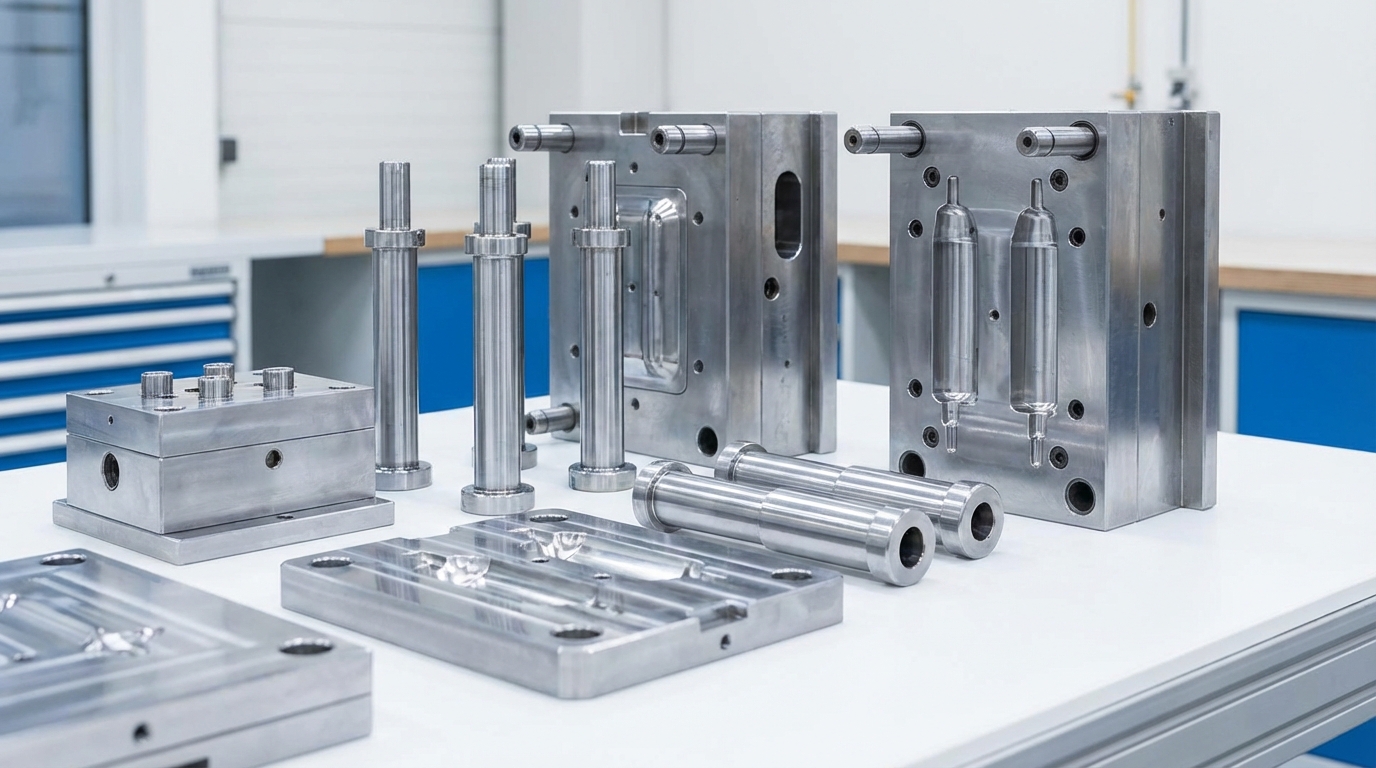
The structure of an injection mold is a sophisticated assembly of precision-engineered parts designed to transform molten resin into high-quality plastic parts. You might be struggling with inconsistent part quality or slow cycle times, which often stem from a lack of understanding regarding how these internal elements interact. By mastering the synergy between injection mold components , you can significantly reduce production downtime and optimize your manufacturing ROI.
What are the core injection mold components?
The core injection mold components are the functional sub-systems that work in unison to facilitate material flow, part shaping, and part removal. These systems include the mold base, the molding system, the feeding system, the ejection system, and the cooling and venting channels.
Why do these systems matter?
Think about it: every part of the mold has a specific job to ensure the final product meets your tolerances. If one component fails, the entire production line stops.
- Mold Base: The rigid framework.
- Molding System: The cavity and core.
- Feed System: The pathway for molten plastic.
Look: you cannot expect high-volume success without a robust mechanical foundation.
How do they interact?
Here is the deal: the feeding system delivers material to the molding system, which then requires the cooling system to solidify the part before the ejection system takes over.
- Precise timing is critical.
- Thermal balance prevents warping.
- Mechanical alignment stops flash.
Key Takeaway: Understanding these sub-systems allows you to diagnose production issues faster and ensure a smoother manufacturing process.
| System | Primary Function | Key Parts | |
|---|---|---|---|
| Mold Base | Structural Support | A/B Plates, Spacer Blocks | |
| Molding System | Part Shaping | Cavity, Core, Sliders | |
| Feeding System | Material Transport | Sprue, Runners, Gates |
The integration of these systems determines the mechanical integrity and longevity of the entire tool.
How does the base hold injection mold components?
The mold base acts as the semi-finished framework or “skeleton” that provides rigid structural support for all other injection mold components. It consists of various steel plates, such as the top clamp plate, A plate, B plate, and the rear clamp plate, which are bolted together to withstand immense clamping forces.
What is the role of plates?
The A and B plates are perhaps the most vital because they house the cavity and core inserts. They must be perfectly parallel to prevent the molten plastic from leaking out during the injection phase.
- Top Clamp Plate: Secures the mold to the machine.
- A Plate: Holds the stationary cavity.
- B Plate: Houses the moving core.
The best part? Standardizing these bases allows for easier maintenance and faster mold changes.
Why are spacer blocks used?
Look: the spacer blocks, often called the C plate, create the necessary clearance for the ejection system to operate. Without this space, your ejector pins wouldn’t have the room to move forward and push the part out.
- Creates the “ejector box.”
- Supports the rear clamp plate.
- Dictates the maximum ejection stroke.
Key Takeaway: A high-quality mold base prevents plate deflection, ensuring your parts remain dimensionally accurate over thousands of cycles.
| Plate Name | Function | Material Priority | |
|---|---|---|---|
| A Plate | Cavity Support | High Hardness Steel | |
| B Plate | Core Support | High Hardness Steel | |
| C Plate | Spacing | Structural Steel |
Proper plate selection is the first step in avoiding mechanical failures under the high pressures of mass production.
Can feed systems guide injection mold components?
Yes, the feed system manages the flow of molten resin from the machine nozzle into the cavities occupied by other injection mold components . This system is comprised of the sprue, runners, sub-runners, and the gates that act as the final entry point for the material.
How does the runner work?
Think about it: the runner is like a highway for plastic, and its design dictates how quickly and evenly the cavities are filled. If the runner is too small, you face pressure drops; if it is too large, you waste material.
- Sprue: The main entry channel.
- Runners: Distribution channels to cavities.
- Cold Slug Well: Captures the initial cold plastic.
But wait, there’s more: a well-designed runner system minimizes the “frozen-in” stresses that lead to part deformation.
What is the gate’s function?
Here is the deal: the gate is the most sensitive area because it controls the flow rate and when the material “freezes off” after injection. Choosing between a sub-gate or a pin-point gate depends entirely on your aesthetic and functional requirements.
- Controls fill time.
- Impacts part surface finish.
- Affects the ease of part degating.
Key Takeaway: Optimizing the feed system is essential for achieving a balanced fill, which prevents defects like short shots or air traps.
| Feed Element | Impact on Quality | Common Issue | |
|---|---|---|---|
| Sprue | Fill Speed | Long Cycle Time | |
| Runner | Pressure Balance | Hesitation Marks | |
| Gate | Surface Finish | Gate Vestige |
An efficient feed path ensures that every cavity receives the same material pressure for consistent part weight.
Which systems shape our injection mold components?
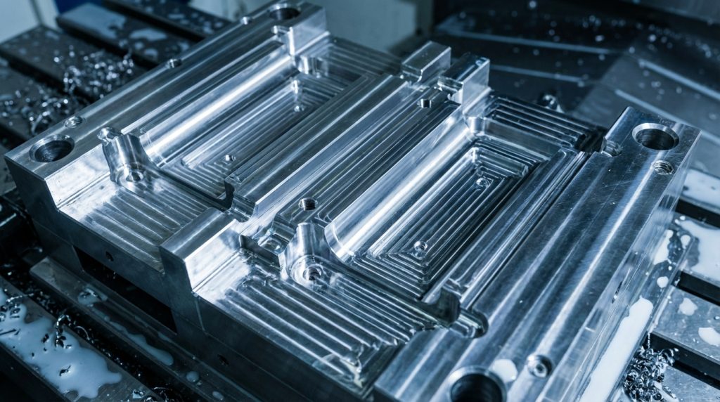
The molding system, consisting primarily of the cavity and core, is the specialized section that gives the final shape to all injection mold components. The cavity defines the external appearance and “A-side” finish, while the core creates the internal geometry and “B-side” features.
How do core and cavity differ?
The cavity is generally the stationary side of the mold, while the core is the moving side that allows for part ejection. They must fit together with microscopic precision to create the void that the plastic fills.
- Cavity: Defines external aesthetics.
- Core: Defines internal structural features.
- Sliders: Handle side-action undercuts.
The best part? Using high-grade tool steel for these inserts ensures they can handle millions of cycles without wearing down.
Why are lifters necessary?
Look: if your part has internal undercuts, you need lifters to release those features before the part can be ejected. These components move at an angle to clear the geometry without damaging the plastic.
- Clears internal undercuts.
- Driven by the ejector plate.
- Requires precise draft angles.
Key Takeaway: The molding system is the “soul” of the mold, directly responsible for the dimensional accuracy and surface quality of your parts.
| Component | Function | Geometry Focus | |
|---|---|---|---|
| Mold Cavity | Front-side shaping | Aesthetics | |
| Mold Core | Back-side shaping | Structure | |
| Lifter | Undercut release | Internal detail |
This system requires the most significant investment in precision machining to ensure the final product meets your specifications.
How do pins eject injection mold components?
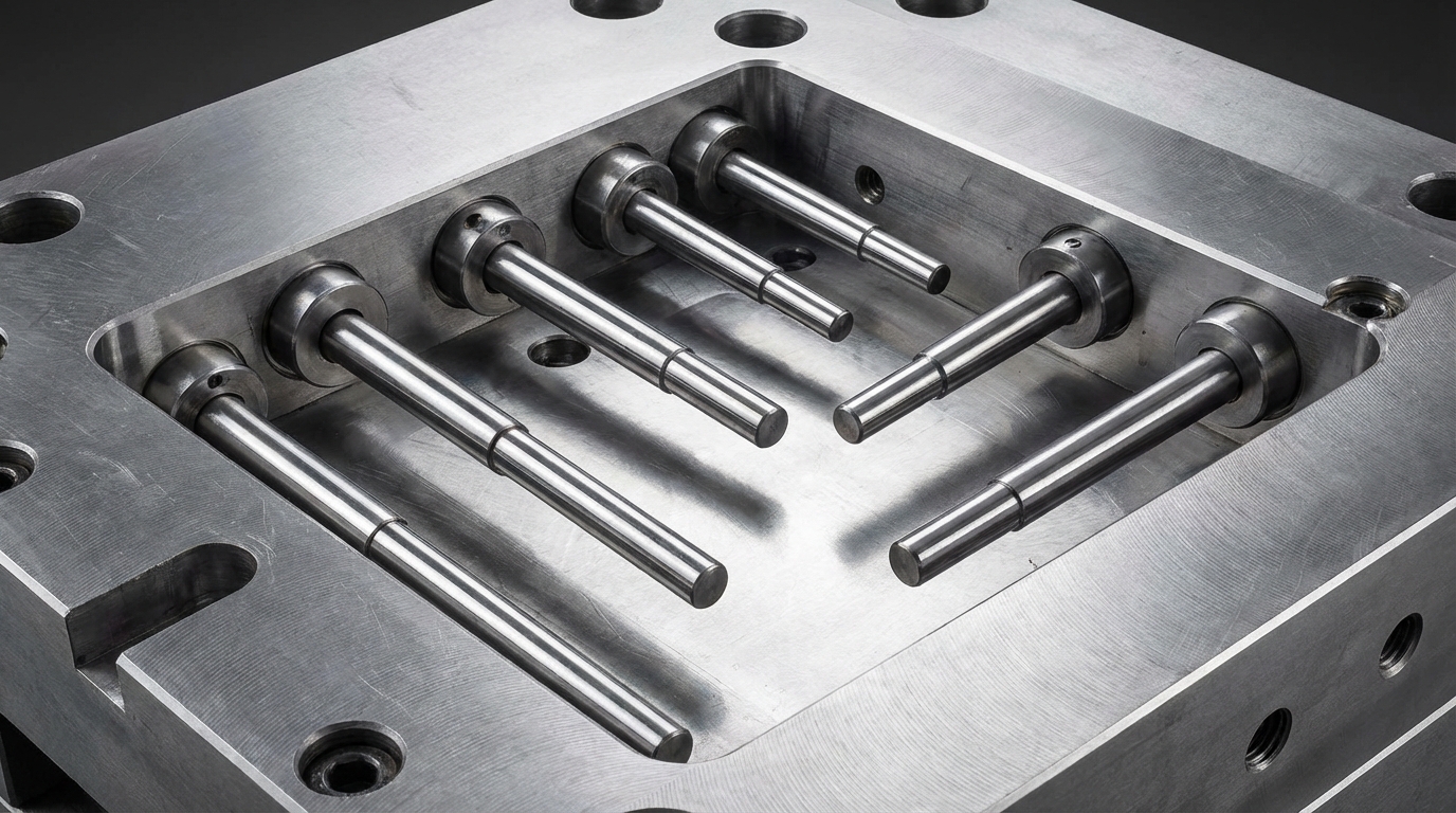
Ejector pins are the mechanical force used to push the solidified plastic part off the core and away from other injection mold components . These pins are mounted on an ejector plate assembly which is moved forward by the injection molding machine’s hydraulic or electric actuators.
How are pins designed?
Think about it: if you don’t have enough pins, or if they are in the wrong place, the part might bend or crack during ejection. You need to place them where the part is strongest, such as along ribs or bosses.
- Ejector Pins: Standard round pushing rods.
- Ejector Sleeves: Best for cylindrical parts.
- Return Pins: Ensure the system resets properly.
The best part? Standardized pins are easy to replace if they become worn or broken during high-speed runs.
What about part stress?
Here is the deal: excessive ejection force can cause “whitening” or stress marks on the plastic. A balanced ejection system ensures that the force is distributed evenly across the part’s surface.
- Uniform pressure is key.
- Draft angles reduce friction.
- Polished surfaces aid release.
Key Takeaway: A reliable ejection system prevents part damage and ensures that your machine can maintain a fast, continuous cycle.
| Ejection Part | Application | Advantage | |
|---|---|---|---|
| Standard Pin | General surfaces | Cost-effective | |
| Sleeve | Circular bosses | Even pressure | |
| Blade | Thin-walled ribs | Precise reach |
Selecting the right ejection method is crucial for maintaining the cosmetic integrity of your finished products.
Does cooling help all injection mold components?
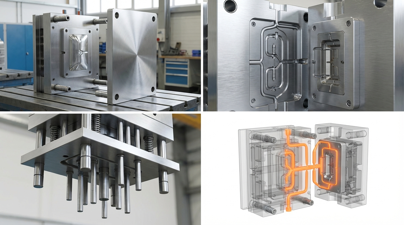
Yes, the cooling system regulates the temperature of all injection mold components to ensure consistent solidification of the plastic material. This is typically achieved through a network of drilled channels, known as water lines, through which coolant or water circulates at a controlled temperature.
How does cooling impact cycles?
Think about it: cooling usually accounts for over 60% of the total injection molding cycle time. By optimizing the placement of these channels, you can drastically reduce the time it takes for a part to be ready for ejection.
- Baffles: Direct flow into deep cores.
- Bubblers: Cool narrow, tall features.
- Thermal Pins: Rapid heat transfer in tight spots.
Look: uneven cooling is the primary cause of warping and sink marks in molded parts.
Can cooling extend mold life?
Here is the deal: consistent temperature control reduces the thermal stress on the steel plates and inserts. This prevents the metal from expanding and contracting excessively, which can lead to fatigue or cracking over time.
- Stabilizes mold geometry.
- Protects surface finishes.
- Reduces mechanical wear.
Key Takeaway: Efficient cooling is not just about speed; it is about maintaining the thermal equilibrium required for high-quality production.
| Cooling Method | Best Use Case | Efficiency | |
|---|---|---|---|
| Standard Channels | Flat plates | Medium | |
| Baffles/Bubblers | Complex cores | High | |
| Conformal Cooling | Irregular shapes | Very High |
Investing in advanced cooling strategies often pays for itself through significantly faster production rates.
Why do vents save your injection mold components?
Venting protects your injection mold components by allowing trapped air and gases to escape as the molten plastic fills the cavity. Without proper venting, the compressed air can reach high enough temperatures to burn the plastic and damage the steel surface of the mold.
Where should vents be placed?
Think about it: air will naturally be pushed to the last place the plastic fills. You must place vent grooves at the end of the fill paths and near knit lines to prevent defects.
- Parting Line Vents: The most common location.
- Ejector Pin Venting: Uses the pin clearance.
- Venting Plugs: Specialized porous inserts.
The best part? Good venting eliminates “diesel effect” burns and ensures the part fills completely.
How deep should vents be?
Here is the deal: if a vent is too deep, the plastic will flow into it and create “flash.” If it is too shallow, the air cannot escape fast enough, leading to air traps and short shots.
- Depth varies by resin viscosity.
- Width should be maximized.
- Regular cleaning prevents clogging.
Key Takeaway: Proper venting is the secret to achieving high-quality surface finishes and preventing costly damage to your mold inserts.
| Venting Type | Location | Target Problem | |
|---|---|---|---|
| Groove | Parting line | General air traps | |
| Pin Gap | Deep ribs | Vacuum prevention | |
| Porous Metal | Blind pockets | Gas burns |
Effective venting is a critical design detail that differentiates amateur tools from professional production molds.
How do guide pins seat injection mold components?
Guide pins and bushings are the alignment injection mold components that ensure the two halves of the mold meet with perfect precision every time. They prevent the core and cavity from shifting during the high-pressure injection process, which would otherwise result in uneven wall thicknesses or part mismatch.
Why is alignment critical?
Think about it: even a shift of 0.01mm can cause noticeable flaws in high-precision parts. Guide pins take the initial load as the mold closes, protecting the delicate molding surfaces from impact.
- Guide Pins: Hardened steel pillars.
- Guide Bushings: Mating wear-resistant holes.
- Interlocks: Provide additional side-load support.
Look: without these, your mold inserts would quickly deteriorate due to repetitive misalignment.
How do they handle wear?
Here is the deal: because these parts move against each other constantly, they are designed to be replaceable wear items. Using self-lubricating bushings can reduce maintenance requirements and prevent galling.
- Requires regular lubrication.
- Hardness must exceed plate steel.
- Lead-in chamfers aid entry.
Key Takeaway: The guiding system is the guardian of your mold’s precision, ensuring that the tool remains functional for millions of cycles.
| Alignment Part | Function | Material | |
|---|---|---|---|
| Guide Pin | Primary direction | SUJ2 Hardened Steel | |
| Guide Bushing | Precise mating | Bronze/Steel | |
| Side Lock | High-clamping stability | Hardened Steel |
Proper maintenance of the guiding system is non-negotiable for anyone looking to achieve long-term manufacturing consistency.
Ready to optimize your injection mold components?
Optimizing your injection mold components is the only way to ensure your B2B manufacturing operations remain competitive and profitable. By focusing on the structural integrity, thermal balance, and precision alignment of these parts, you solve common production headaches before they start.
At CN Precision, we specialize in high-precision tooling and IATF 16949-certified molding solutions. We understand that your reputation depends on the quality of every single part that leaves the mold. Whether you need a complex 2K tool or a high-volume production mold, our engineering team is here to provide the DFM support and technical expertise you need.
Don’t let subpar mold design slow your growth. If you are ready to elevate your product quality and reduce your total cost of ownership, contact us today for a free technical consultation and quote. We are your trusted partner in precision manufacturing, dedicated to delivering excellence in every component.
Any questions on these injection mold components?
Can I replace individual components if they break?
Yes, most professional molds are designed with modular inserts and standardized pins to allow for easy replacement. This modularity ensures you don’t have to rebuild the entire tool if a specific rib or pin fails during production.
How often should I lubricate guide pins?
You should lubricate them at least once per shift or every 24 hours of continuous operation. Regular lubrication prevents friction-related heat and “galling,” which can seize the mold and cause significant mechanical damage.
Can cooling lines be added after the mold is made?
It is difficult and expensive because the cooling path must avoid all pins, screws, and sliders. Proper thermal management should be finalized during the initial DFM and design phase to ensure maximum efficiency.
Why does my mold have black spots on the part?
This is usually caused by inadequate venting, where trapped air burns the plastic due to high compression. Increasing the vent depth or adding more vents along the parting line typically solves this issue.
Do I need sliders for every undercut?
Not necessarily, as some external undercuts can be handled by “stripper” plates or simplified mold actions. However, for complex side features, sliders are the most reliable way to ensure the part releases without deformation.