Designing molded parts effectively involves mastering geometry, material flow, and tooling constraints to ensure high-quality manufacturability. You might find that parts prototyped via 3D printing often fail when transitioning to mass production due to overlooked technical constraints. These failures lead to expensive tooling reworks, cosmetic defects, and significant project delays that hurt your bottom line. Proper plastic mold design integrates specific engineering principles like draft and uniform wall thickness to streamline your manufacturing process from the start.
Why is draft essential in plastic mold design?
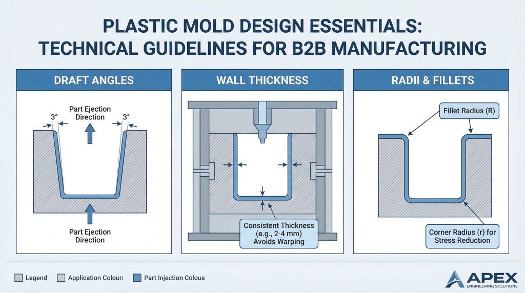
Draft is essential because it allows the part to release from the mold without surface damage or excessive friction during the ejection phase. When you implement a strategic plastic mold design , you ensure that the material, which shrinks onto the mold core during cooling, can be pushed out easily. Without this taper, the vacuum created between the part and the steel can cause scuffing or even part breakage.
How Draft Prevents Part Drag and Surface Damage
Applying draft reduces the amount of pressure required by the ejection system to move the part. Think about it: a perfectly vertical wall will rub against the mold surface for the entire duration of the ejection stroke. This friction often results in unsightly “drag marks” that ruin the cosmetic finish of your product. By adding just a small angle, the part breaks contact with the mold immediately upon movement.
Recommended Degrees for Easy Ejection
A common industry standard is to provide at least one degree of draft for every inch of cavity depth. However, you should consider increasing this angle if you are using a textured finish, as the “peaks” of the texture need more clearance to avoid being crushed. Higher-shrinkage resins may also require more generous angles to compensate for their tighter grip on the core.
Calculating Draft Based on Cavity Depth
Calculating the correct angle is a balance between part function and manufacturing feasibility. You must evaluate the depth of the vertical ribs and walls to ensure the taper does not make the top of the feature too thin. Here is the kicker: deeper cavities require more draft to ensure the part remains dimensionally stable while still releasing smoothly.
Key TakeawayAdding draft is the most critical step to prevent part deformation and surface scuffing during the final stages of the molding cycle.
| Feature Type | Standard Draft | Textured Draft | |
|---|---|---|---|
| External Walls | 1° – 2° | 3° – 5°+ | |
| Internal Ribs | 0.5° – 1° | N/A | |
| Deep Pockets | 2°+ | 5°+ |
The following table highlights how specific feature types dictate the necessary taper required for successful part ejection.
How does wall thickness impact plastic mold design?
Wall thickness impacts the cooling rate and structural integrity of your part, where uneven thickness often causes warping or sink marks. In any successful plastic mold design, maintaining a consistent thickness is the “golden rule” for achieving high-quality results. If you design parts with sections that are too thick, you risk creating internal voids or unsightly surface depressions.
Preventing Sink, Warp, and Internal Voids
When a part has thick sections, the exterior cools and hardens while the interior remains molten and continues to shrink. This internal shrinkage pulls the outer surface inward, creating a “sink mark” that is difficult to hide even with texturing. Warp occurs when different areas of the part cool at different rates, leading to internal stresses that twist the final product.
- Maintain a uniform wall thickness throughout the entire part geometry.
- Use a 40% to 60% ratio for rib-to-wall thickness to prevent localized sinking.
- Avoid transitions between thick and thin sections whenever possible.
- Design for the thinnest wall that still meets your structural requirements.
Maintaining Uniformity for Better Cooling
Uniform walls allow the mold’s cooling channels to extract heat evenly across the entire surface area. The truth is: parts with varying thicknesses take much longer to cycle because the machine must wait for the thickest section to solidify. By optimizing thickness, you not only improve quality but also decrease your overall cycle time and production costs.
Key TakeawayConsistent wall thickness ensures balanced cooling, which is the primary defense against cosmetic defects like sink and structural issues like warp.
| Resin Material | Recommended Thickness (Inches) | Max Thickness (Inches) | |
|---|---|---|---|
| ABS | 0.045 – 0.140 | 0.150 | |
| Nylon | 0.030 – 0.115 | 0.125 | |
| Polycarbonate | 0.040 – 0.150 | 0.160 |
This data provides a baseline for selecting wall thicknesses that align with the flow characteristics of common engineering resins.
What role do radii play in effective plastic mold design?
Radii act as smooth transitions that reduce stress concentrations and allow molten resin to flow effortlessly through the tool. Within an effective plastic mold design , replacing sharp corners with rounded edges prevents the plastic from “shearing” as it moves. This design choice mimics natural flow patterns, ensuring the cavity fills completely without trapping air or causing material degradation.
Improving Material Flow Like a Natural River
Think of the resin filling your mold like water flowing through a river. Rivers don’t have 90-degree turns because water naturally erodes corners to create smooth, curved paths of least resistance. Similarly, plastic resin flows better around soft corners, which minimizes the pressure required from the injection molding machine to fill the mold.
Reducing Stress Concentration in Sharp Corners
Sharp internal corners are notorious for acting as “stress risers” where cracks are likely to initiate under load. By adding a radius, you distribute the mechanical load over a larger area, significantly increasing the part’s impact resistance. But wait, there’s more: rounded corners also help the part release from the mold more easily by reducing the surface area where the part could stick.
Enhancing Part Integrity and Structural Strength
A well-placed radius improves the overall structural integrity of features like bosses and ribs. It prevents the sharp “notch effect” that often leads to premature part failure in the field. You should aim for an inside radius that is at least 50% of the wall thickness and an outside radius of 150% to maintain constant wall thickness.
Key TakeawayUtilizing radii converts sharp, weak points into strong, flow-friendly transitions that enhance both the manufacturing process and the final product’s durability.
| Feature | Min Radius | Benefit | |
|---|---|---|---|
| Internal Corner | 0.5 x Wall Thickness | Reduces Stress | |
| External Corner | 1.5 x Wall Thickness | Consistent Walls | |
| Rib Base | 0.25 x Wall Thickness | Prevents Cracking |
Strategic use of radii as shown here directly correlates to improved part longevity and reduced manufacturing defects.
How to use ribs and gussets in plastic mold design?
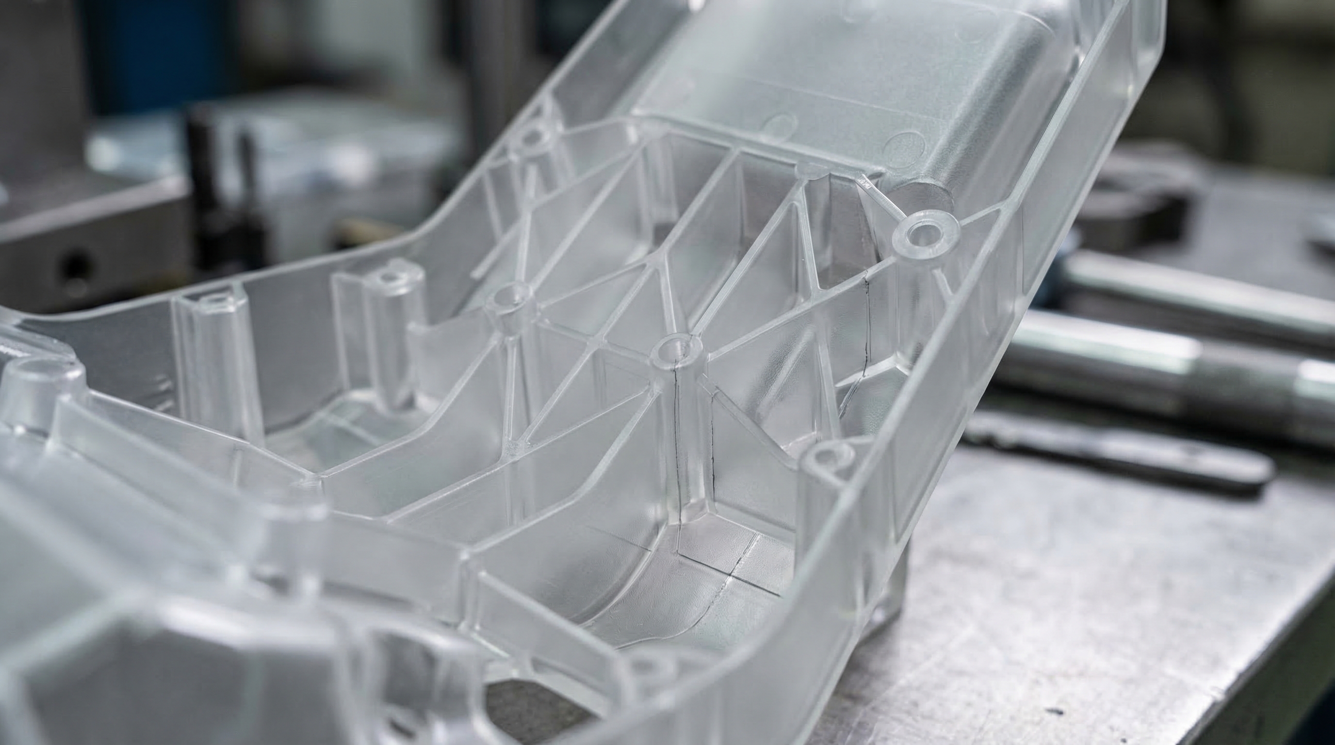
Ribs and gussets add structural rigidity to thin-walled parts without increasing material volume or increasing cooling times. A sophisticated plastic mold design utilizes these features to provide strength exactly where it is needed while keeping the primary walls thin. This approach allows you to create lightweight parts that are just as strong as solid, thick-walled components.
The Ideal Rib-to-Wall Thickness Ratio
The most effective way to design ribs is to keep them between 40% and 60% of the thickness of the adjacent wall. If you make the rib too thick, you will inevitably create sink marks on the “A-side” of the part where the rib attaches. Let’s dive deeper: properly sized ribs solidify quickly, ensuring the rest of the part doesn’t have to wait for the support structures to cool.
- Keep rib height less than three times the wall thickness.
- Apply at least 0.5 degrees of draft to all rib surfaces.
- Space ribs at least two times the wall thickness apart.
- Use multiple small ribs rather than one large, thick rib.
Coring Out Thick Sections Without Losing Strength
Instead of designing a solid block, you should “core out” the part to maintain a uniform wall and add ribs for stiffness. This technique reduces material usage and prevents the formation of internal voids that can weaken the structure. In short: coring out provides a professional aesthetic while maintaining the mechanical performance required for industrial applications.
Using Ramps and Gussets for Smooth Transitions
Gussets are small triangular supports that reinforce the connection between two surfaces, such as a vertical boss and a flat base. They provide lateral support without the risk of adding significant mass that would lead to cooling issues. Using ramps to transition between different heights also helps the plastic flow smoothly, reducing the molding stresses that cause warping.
Key TakeawayRibs and gussets are the primary tools for achieving high structural strength while adhering to the essential rule of thin, uniform wall design.
| Support Type | Recommended Size | Primary Function | |
|---|---|---|---|
| Support Rib | 50% Wall Thickness | Vertical Stiffness | |
| Corner Gusset | 40% Wall Thickness | Lateral Support | |
| Structural Ramp | 3:1 Slope | Flow Transition |
These support structures allow you to optimize part performance without compromising the cosmetic quality of the exterior surfaces.
Is the core-cavity method better for plastic mold design?
The core-cavity method is superior for deep-walled parts because it creates parallel drafted walls that simplify ejection and cooling. In plastic mold design , this approach involves designing the part so that its walls are formed by two different halves of the mold fitting together. This is much more efficient than cutting a deep, narrow slot into a single block of steel.
Differences Between A-Side and B-Side Tooling
The A-side (cavity) usually forms the exterior, cosmetic surface of your part, while the B-side (core) contains the internal features and ejection system. By splitting the design this way, you can achieve better surface finishes on the visible parts of your product. The best part? The core side naturally grips the part as it shrinks, ensuring it stays on the side where the ejector pins are located.
Creating Parallel Drafted Walls for Efficiency
When you use the core-cavity method, the inside and outside walls are drafted in the same direction, making them parallel. This maintains a perfectly consistent wall thickness even as the part gets deeper. Here is the kicker: consistent thickness means the part cools at the same rate throughout, drastically reducing the likelihood of warping or internal stress.
Reducing Tooling Costs and Manufacturing Time
Manufacturing a mold with a core-cavity design is often faster and cheaper because the shop can use larger, more robust cutting tools. Instead of using tiny end mills to reach the bottom of a deep, thin rib, the machinist can mill the core and cavity separately with ease. This reduces the risk of tool breakage and shortens the overall lead time for your project.
Key TakeawayThe core-cavity approach is a strategic design choice that lowers manufacturing costs while improving part quality and cooling efficiency.
| Approach | Machining Difficulty | Part Quality | |
|---|---|---|---|
| Deep Rib Method | High (Requires thin tools) | Lower (Risk of warp) | |
| Core-Cavity Method | Low (Uses standard tools) | Higher (Uniform walls) |
Comparing these two methods clearly demonstrates why the core-cavity approach is preferred for complex, deep-profile molded parts.
How are undercuts managed in plastic mold design?
Undercuts are managed using side-actions, lifters, or manual inserts to release features that prevent straight-pull ejection. While a simple plastic mold design is usually preferred for cost, modern manufacturing can handle high complexity through these specialized mechanical solutions. These mechanisms allow you to design parts with side holes, snap-fits, and internal threads that would otherwise be impossible to mold.
Using Pin-Actuated Side-Actions for Complexity
Side-actions (or cams) are mold components that slide out of the way before the part is ejected. These are typically driven by an angled “horn pin” that pulls the side-action back as the mold opens. Think about it: this automation allows you to produce complex parts with through-holes on the side without any manual intervention by the machine operator.
- Use side-actions for external features like side ports or latches.
- Ensure the feature has its own draft in the direction of the slide’s travel.
- Place side-actions on the parting line whenever possible to simplify the mold.
- Budget for higher tooling costs when multiple side-actions are required.
When to Use Manually Removed Inserts
For lower-volume production or extremely complex internal geometries, manual inserts (hand-loads) may be the right choice. An operator places these pieces into the mold before each cycle, and they are ejected along with the part. Afterward, the operator removes the insert from the part and restarts the process. This is a cost-effective way to manage undercuts when the budget doesn’t allow for fully automated slides.
Balancing Design Complexity with Project Budget
Every undercut you add increases the complexity and cost of the mold. The truth is: while side-actions are efficient, they require more maintenance and increase the risk of flash at the parting lines. You must weigh the functional necessity of the undercut against the increased tooling investment and potential impact on cycle times.
Key TakeawayUndercuts are fully manageable with side-actions or inserts, provided you account for the additional tooling costs and maintenance requirements.
| Mechanism | Automation | Cost Level | |
|---|---|---|---|
| Side-Action (Cam) | Fully Automated | High | |
| Internal Lifter | Fully Automated | Very High | |
| Manual Insert | Manual | Low to Medium |
Understanding these mechanisms helps you choose the right balance between part complexity and total production investment.
Which gating style is best for your plastic mold design?
The best gating style depends on your part’s aesthetic requirements, material flow characteristics, and the need for automatic de-gating. In your plastic mold design , the gate is the “doorway” through which molten plastic enters the cavity. Choosing the right style ensures the part fills evenly while minimizing the visible “scar” or vestige left behind.
Tab Gates vs. Sub Gates for Minimal Vestiges
Tab gates are the most common and reliable because they allow for high flow rates and are easy to size during the sampling phase. However, they must be manually trimmed, leaving a small vestige on the edge of the part. Sub gates (or tunnel gates) are often preferred for high-volume runs because they automatically shear off during ejection, eliminating the need for manual secondary operations.
Benefits of Hot Tip Gates for Balanced Fill
Hot tip gates are used in hot runner systems where the plastic stays molten all the way to the part surface. This style leaves only a tiny, circular vestige that can often be hidden inside a logo or a recessed area. Let’s dive deeper: hot tips are excellent for parts that require a perfectly balanced fill from the center outward, which reduces the risk of part warping.
Dealing with Direct Sprue Gates and Glass Content
Direct sprue gates are typically used for large, heavy-walled parts or materials with very high glass-fiber content. Because the gate is so large, it allows the material to flow without shearing the fibers, maintaining the structural strength of the resin. The downside is that these gates leave a very large vestige that almost always requires secondary machining or grinding to remove.
Key TakeawayGating selection is a trade-off between the cost of secondary labor and the aesthetic requirements of the final molded part.
| Gate Type | Auto De-Gating | Vestige Size | |
|---|---|---|---|
| Tab Gate | No | Medium | |
| Sub Gate | Yes | Small | |
| Hot Tip | Yes | Minimal |
This table serves as a guide for selecting a gate style that meets your production volume and cosmetic standards.
How to reduce costs through plastic mold design?
You can reduce costs by simplifying geometry, minimizing secondary operations, and optimizing cycle times through efficient cooling. A cost-conscious plastic mold design focuses on “straight-pull” parts that do not require expensive side-actions or lifters. By designing for manufacturability from day one, you avoid the high fees associated with complex tooling and long production runs.
Minimizing Secondary Operations and Machining
The most expensive part of molding is often the labor required after the part leaves the machine. If you can design your part to be self-mating or snap-fit, you eliminate the need for screws, adhesives, or ultrasonic welding. In short: the more work you can make the mold do during the cycle, the less you will pay for assembly and finishing.
- Eliminate undercuts to avoid the cost of side-actions.
- Use a “self-degating” sub gate to remove manual trimming labor.
- Optimize surface finishes to avoid the need for painting or plating.
- Design parts with integrated fasteners to reduce assembly steps.
Optimizing Part Geometry for Faster Cycles
Cycle time is money in the world of injection molding. The best part? By following wall thickness guidelines, you ensure that parts solidify as quickly as possible, allowing the machine to run more cycles per hour. Even a one-second reduction in cycle time can save thousands of dollars over a large production run of 100,000 parts or more.
Selection of Efficient Tooling Methods
Depending on your production volume, you might choose between aluminum and steel molds. Aluminum tools are much faster to machine and cool more quickly, making them ideal for prototyping and low-to-medium volume production. For millions of parts, hardened steel is necessary for durability, but the upfront cost is significantly higher.
Key TakeawayCost reduction is achieved by prioritizing simplicity in design and maximizing the efficiency of the molding cycle.
| Cost Driver | Reduction Strategy | Impact | |
|---|---|---|---|
| Tooling Complexity | Eliminate Undercuts | -20% to -40% | |
| Cycle Time | Thinner Walls | -10% to -30% | |
| Labor | Auto-Degating | -5% to -15% |
Implementing these strategies during the design phase ensures your project remains within budget while maintaining high quality.
Why is DFM analysis critical for plastic mold design?
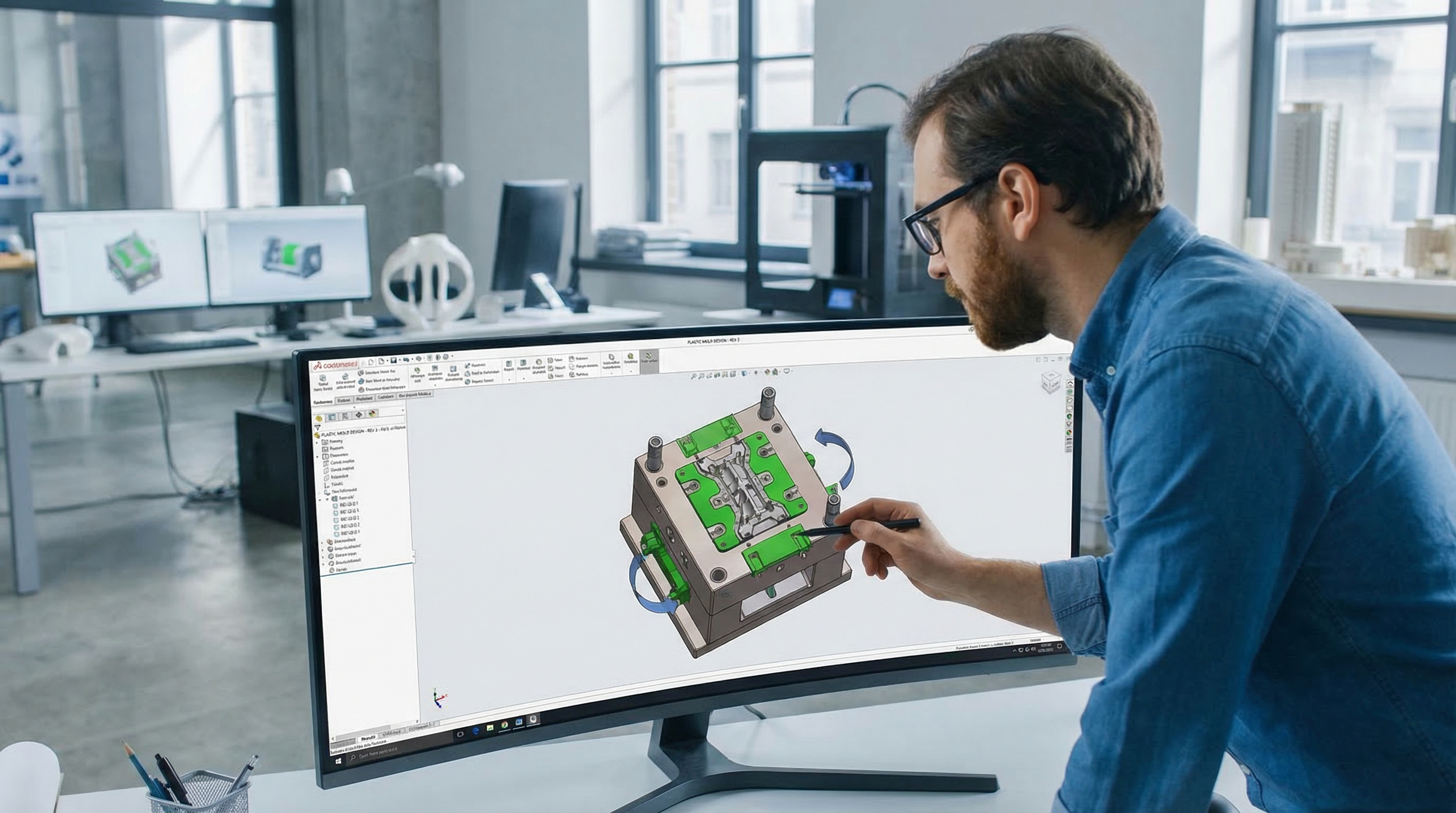
DFM analysis is critical because it identifies manufacturing risks like thin steel, poor venting, or high-stress areas before you cut metal. When you submit a plastic mold design for review, advanced software and experienced engineers check every feature for potential failure. This proactive step ensures that the mold will perform reliably from the first shot to the last.
Identifying Manufacturability Issues Early
Catching a mistake in a CAD file costs almost nothing, but fixing a mistake in a hardened steel mold can cost thousands of dollars. DFM analysis looks for “thin steel” conditions where the mold might be too fragile and could break under high injection pressures. Here is the kicker: identifying these issues early allows you to modify the geometry without affecting the overall project timeline.
Comparing Part Geometry to Tooling Capabilities
Not every part that can be designed in CAD can be easily machined into a mold. DFM analysis compares your part features to the available toolsets, such as end mill lengths and diameters. If a feature is too deep and narrow for a standard cutter to reach, the analysis will flag it, allowing you to widen the rib or increase the draft.
Validating Design Logic Before Cutting Steel
Before you commit to a major tooling investment, you need to know that your design logic is sound. Analysis tools can simulate the “mold flow,” showing you exactly how the plastic will fill the cavity and where potential weld lines or air traps might occur. This validation gives you the confidence to proceed with production knowing that the parts will meet your specifications.
Key TakeawayDFM analysis is your insurance policy against unexpected tooling failures and expensive post-production modifications.
| Analysis Type | Focus Area | Goal | |
|---|---|---|---|
| Draft Check | Vertical Walls | Easy Ejection | |
| Wall Thickness | Cross-Sections | Prevent Sink | |
| Flow Simulation | Fill Pattern | Eliminate Voids |
The following table summarizes the key areas covered during a comprehensive manufacturability review.
How does material choice affect plastic mold design?
Material choice dictates the specific shrinkage rates, gate sizes, and cooling requirements needed to achieve dimensional accuracy. Every resin has a unique “shrinkage” factor that must be accounted for in the plastic mold design by making the mold cavity slightly larger than the final part. If you change materials after the mold is built, the part may no longer fit its intended assembly.
Understanding Resin-Specific Flow Characteristics
Some plastics, like Polypropylene, flow very easily and can fill thin, complex features without high pressure. Others, like Polycarbonate, are much more viscous and require larger gates and thicker walls to fill the mold properly. Think about it: the flow characteristics of your material will determine how many gates you need and where they should be placed to ensure a complete fill.
- Amorphous resins (ABS, PC) generally have lower shrinkage.
- Crystalline resins (Nylon, PE) have higher shrinkage and require more cooling.
- Glass-filled resins increase strength but can cause tool wear.
- High-flow resins allow for thinner walls and more complex geometries.
Impact of Glass Content on Gating Selection
Adding glass fibers to a resin makes the final part much stiffer and more heat-resistant, but it also changes how the material behaves in the mold. Glass fibers tend to align with the direction of flow, which can cause the part to warp if the gating is not positioned correctly. You must use larger gates and avoid sharp turns to prevent the fibers from breaking during the injection process.
Predicting Shrinkage Rates for Tooling Accuracy
The truth is: predicting shrinkage is as much an art as it is a science. Factors like injection pressure, melt temperature, and cooling time all influence how much the final part will shrink. Experienced mold designers use material data sheets and historical results to “oversize” the mold just enough so that the part shrinks down to the exact dimensions required upon cooling.
Key TakeawaySelecting your material early in the design process is vital because the resin’s properties directly dictate the physical dimensions of the mold.
| Resin Type | Typical Shrinkage (in/in) | Flow Ability | |
|---|---|---|---|
| ABS | 0.005 – 0.007 | High | |
| Polycarbonate | 0.005 – 0.008 | Low | |
| Nylon 6/6 | 0.010 – 0.015 | Medium |
This table illustrates the wide variance in shrinkage rates that must be managed during the mold engineering process.
Summary and Next Steps
Mastering the basics of injection molding is the foundation of successful product development. By integrating essential elements like draft, uniform wall thickness, and strategic radii, you ensure that your designs are not only functional but also optimized for mass production. These principles minimize manufacturing defects, reduce tooling costs, and accelerate your time-to-market.
At CN Precision, we are committed to being more than just a vendor; we are your strategic manufacturing partner. Our IATF 16949 certified facilities and expert engineering team are dedicated to delivering precision-engineered parts that meet the most demanding standards of the automotive, medical, and electronics industries. We believe that professional technical guidance is the key to solving complex manufacturing challenges and ensuring your project’s success.
Actionable Guidelines:
- Review Draft: Ensure all vertical surfaces have at least 1 degree of taper.
- Verify Walls: Maintain uniform thickness within the recommended range for your selected resin.
- Consult Engineers: Utilize professional DFM analysis before finalizing your tooling order.
- Optimize Gating: Choose a gate style that balances aesthetics with production efficiency.
| Final Design Checklist | Completed | |
|---|---|---|
| Are all corners rounded with appropriate radii? | [ ] | |
| Does the rib-to-wall ratio fall between 40-60%? | [ ] | |
| Have all potential undercuts been identified and managed? | [ ] | |
| Is the material shrinkage factor accounted for in the CAD? | [ ] |
Ready to move from concept to production? Contact us today to schedule a free DFM review and discover how our expertise can bring your project to life with precision and reliability.
Frequently Asked Questions
Can I mold parts without any draft angles?Directly answering, it is technically possible but highly discouraged. The reason is that zero-draft walls create extreme friction and a vacuum during ejection, which almost always results in scuffed surfaces, part deformation, or “sticking” that can damage the mold itself.
What’s the best material for high-strength thin walls?Fiber-reinforced resins like glass-filled Nylon are generally the best choice. The reason is that the internal fibers provide the necessary structural stiffness and impact resistance even at reduced thicknesses where unfilled resins would fail.
How do I know if my part needs side-actions?You know you need side-actions if your part has features that are perpendicular to the direction the mold opens. The reason is that any hole or protrusion that “traps” the mold from pulling straight away requires a moving component to clear the feature before ejection can occur.
Can I change the material after the mold is built?Only if the new material has a very similar shrinkage rate to the original. The reason is that mold cavities are cut to a specific size based on the expected shrinkage of the resin; switching to a material with different shrinkage will result in parts that are either too large or too small for your assembly.
What’s the best way to hide sink marks on a cosmetic part?The best way is to follow the 40-60% rib-to-wall thickness rule and apply a textured finish to the exterior surface. The reason is that texture breaks up the reflection of light, making small surface depressions much less visible to the naked eye.