Draft angle guidelines for injection molding involve applying a slight taper to the vertical faces of a part to ensure easy ejection from the mold tool. Failing to incorporate a proper draft angle injection molding strategy often leads to parts getting stuck, warped, or cosmetically damaged during the manufacturing cycle. You might face frustrating delays and increased costs if your designs lack this essential feature. Fortunately, following professional standards ensures smooth production and high-quality results for your plastic components.
What is the purpose of draft angle injection molding?
The primary purpose of draft angle injection molding is to facilitate the effortless removal of a plastic part from its mold cavity after cooling. By using a specific draft angle injection molding technique, you eliminate the vacuum effect and friction that occurs between the part walls and the metal tool. This prevents the part from dragging against the surface, which could otherwise cause structural failure.
How does draft facilitate part ejection?
Part ejection becomes a seamless process when the walls are tapered away from the direction of the mold opening. This ensures that as soon as the mold opens, the part breaks contact with the metal surface immediately.
Think about it this way:
- Without draft, the plastic shrinks onto the core.
- The friction creates a mechanical lock.
- High ejection force is then required, which can stress the part.
Here is the deal: a few degrees of taper can be the difference between a perfect part and a scrap pile.
| Ejection Factor | Impact of Draft | |
|---|---|---|
| Friction | Significantly Reduced | |
| Ejection Force | Lowered | |
| Part Quality | Protected |
A slight taper ensures that the surface area in contact with the mold decreases the instant the part moves.
Key Takeaway: Proper draft protects your investment by preventing mechanical damage to both the part and the expensive steel mold.
Why use early draft angle injection molding in prototypes?
Using early draft angle injection molding in prototypes allows you to validate the final form and fit of the product before committing to mass production tooling. Even if you are starting with 3D printing or CNC machining, integrating a draft angle injection molding design early prevents major structural surprises later. This proactive approach ensures your assembly remains consistent throughout the development lifecycle.
Ensuring fit and function during assembly
Designing with draft from the start helps you understand how the taper affects the wall thickness and overall dimensions of the part. If you ignore this, your prototype might fit perfectly, but the molded version could fail because the taper altered a critical mating surface.
Consider this point:
- Draft changes the geometry of your part.
- It can impact how internal components sit.
- Early integration prevents the need for “emergency” redesigns.
But consider this: many engineers skip draft in 3D prints only to find their injection molded parts won’t fit the original housing.
| Prototype Stage | Draft Integration | Benefit | |
|---|---|---|---|
| 3D Printing | Optional but Recommended | Validates Fit | |
| CNC Machining | Recommended | Design Consistency | |
| Injection Molding | Mandatory | Production Success |
Matching your prototype design to your production requirements eliminates the risk of costly late-stage modifications.
Key Takeaway: Designing for the future production method during the prototyping phase accelerates your time-to-market and reduces engineering overhead.
What are standard rules for draft angle injection molding?
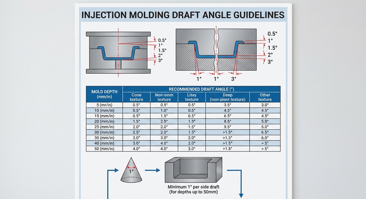
Standard rules for draft angle injection molding suggest applying at least one degree of draft for every inch of cavity depth as a baseline. While this rule is a great starting point for most draft angle injection molding projects, you must adjust it based on material shrinkage and surface finish requirements. Following these benchmarks helps you avoid the most common manufacturing pitfalls.
Recommended minimums for vertical faces
Most professional molders recommend a minimum of 0.5 degrees on all vertical faces to provide basic clearance. However, increasing this to 1 or 2 degrees is often safer for standard materials like ABS or Polypropylene.
Here is the deal:
- 0.5 degrees is the absolute bare minimum.
- 1 degree is standard for smooth surfaces.
- 2 degrees is ideal for deeper parts.
You should always verify these numbers with your manufacturing partner to ensure compatibility with their specific equipment.
| Surface Type | Minimum Draft | Recommended Draft | |
|---|---|---|---|
| Polished | 0.5° | 1.0° | |
| Functional | 1.0° | 2.0° | |
| Ribs/Bosses | 0.5° | 1.5° |
Higher draft angles generally correlate with faster cycle times and fewer part defects on the production line.
Key Takeaway: Adhering to the 1-degree rule provides a safety margin that accommodates most standard thermoplastic behaviors and tool tolerances.
How does depth change draft angle injection molding needs?
Increasing the depth of a feature significantly increases the surface area in contact with the mold, necessitating a larger draft angle injection molding value. Deep features create more friction during ejection, so a one-degree draft on a shallow part may not be sufficient for a four-inch deep cavity. As the depth grows, the draft angle injection molding strategy must scale to maintain ease of release.
Adjusting angles for deep cavity features
For very deep parts, the taper becomes much more pronounced, which can drastically change the wall thickness at the bottom of the cavity. You must balance the need for draft with the requirement to maintain a uniform wall thickness to prevent sink marks.
Take a look at these factors:
- Deep ribs require more taper to vent air.
- Tall walls increase the total drag force.
- Material shrinkage is more impactful on deep cores.
But consider this: a deep part with insufficient draft is essentially a vacuum-sealed piston in a cylinder.
| Feature Depth | Suggested Draft | Note | |
|---|---|---|---|
| < 1 Inch | 1.0° | Standard | |
| 1 – 2 Inches | 1.5° | Safe Zone | |
| > 2 Inches | 2.0°+ | Depth Dependent |
Deep features require a strategic increase in draft to overcome the cumulative friction of the elongated wall surface.
Key Takeaway: Scaling your draft angle proportionally to the depth of the part ensures that the ejection force remains within safe limits for the material.
Why is draft angle injection molding vital for shutoffs?
Draft is vital for shutoffs because it prevents metal-on-metal sliding contact, which can cause galling and premature wear on the mold. In a draft angle injection molding setup, shutoffs occur where the two halves of the mold meet to create a hole or specific feature. Without a dedicated draft angle injection molding angle, the mold components would scrape against each other every time the tool closes.
Minimum requirements for tool shutoffs
A minimum of 3 degrees of draft is typically required for any area where metal slides against metal during the molding cycle. This steep angle ensures that the components only touch at the very last moment of closing, preserving the precision of the tool.
Here is the deal:
- Shutoffs define the “seal” of the part features.
- Friction here leads to flash (leaked plastic).
- Metal wear reduces the life of your expensive tool.
It is absolutely essential to use steep angles for vertical shutoffs to keep your production runs clean and accurate.
| Shutoff Type | Minimum Draft | Purpose | |
|---|---|---|---|
| Vertical Shutoff | 3.0° | Prevent Galling | |
| Sliding Actions | 5.0° | Reduce Wear | |
| Core Pins | 1.0° | Ease Release |
Steep angles on shutoff surfaces are the best way to prevent flashing and extend the operational life of your injection mold.
Key Takeaway: Investing in larger draft angles for shutoffs prevents tool damage and maintains the aesthetic quality of holes and windows in your parts.
How does texture affect draft angle injection molding?
Texture adds micro-undercuts to the surface of a part, which requires a much larger draft angle injection molding to prevent the plastic from locking into the mold. When you choose a textured finish, the draft angle injection molding must be increased by approximately 1.5 degrees for every 0.001 inch of texture depth. Ignoring this rule will result in “drag marks” where the texture is literally scraped off as the part is ejected.
Why heavy textures need 5 degrees or more?
Heavy textures, like those found on automotive dashboards or tool handles, create significant mechanical interference. To clear these microscopic pits and valleys, you need a substantial angle to lift the part away from the texture before moving it laterally.
Think about these requirements:
- Light bead blast (PM-T1) needs 3°.
- Medium bead blast (PM-T2) needs 5°.
- Heavy leather grains may need 7° or more.
But consider this: if you want a beautiful textured part, you must be willing to give up perfectly vertical walls.
| Texture Grade | Recommended Draft | Example Use | |
|---|---|---|---|
| Smooth/Polished | 1.0° | Consumer Electronics | |
| Light Texture | 3.0° | Interior Trim | |
| Heavy Texture | 5.0°+ | Industrial Tools |
Textured surfaces act like thousands of tiny hooks, making a steep draft angle the only way to release the part without damage.
Key Takeaway: Always consult your molder’s texture guide early to ensure your part geometry can support the draft required for your desired finish.
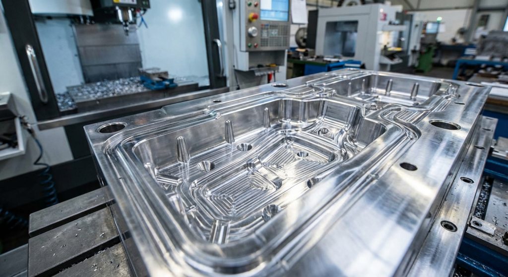
Why use core-cavity for draft angle injection molding?
Using a core-cavity approach in draft angle injection molding allows you to design walls that are parallel to each other, which simplifies the manufacturing and cooling process. In this draft angle injection molding configuration, the mold creates the internal and external surfaces simultaneously, which helps in maintaining uniform wall thickness. This method is especially effective for enclosures and box-like structures.
Improving the ease of mold polishing
When a mold is designed with a core-cavity split, the interior surfaces are more accessible for polishing and maintenance. This results in a better surface finish on the part and allows the molder to reach tight corners that would be impossible to service in a deep-rib design.
Consider these advantages:
- Easier to vent trapped air.
- Faster cooling cycles.
- Improved dimensional stability.
Here is the deal: core-cavity design is the professional way to handle complex enclosures while ensuring they can be ejected reliably.
| Design Approach | Ease of Ejection | Surface Finish Quality | |
|---|---|---|---|
| Deep Rib | Difficult | Variable | |
| Core-Cavity | Excellent | High/Consistent | |
| Zero Draft | Impossible | Damaged |
A core-cavity strategy optimizes the physics of the molding process by distributing draft across both halves of the tool.
Key Takeaway: Implementing a core-cavity approach reduces manufacturing complexity and ensures your parts have consistent quality and faster production times.
How does draft angle injection molding stop mold drag?
Draft stops mold drag by creating an immediate air gap between the cooling plastic and the metal cavity walls. Without this draft angle injection molding gap, the natural shrinkage of the plastic creates high surface tension that makes the part “stick” to the tool. By incorporating a draft angle injection molding slope, you ensure that the friction is broken the moment the ejection pins begin their stroke.
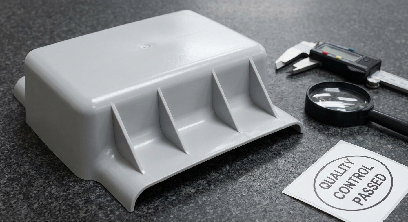
Eliminating scratches on polished surfaces
Mold drag often manifests as unsightly vertical scratches or scuff marks on the sides of a finished part. This is particularly problematic for high-gloss parts where even the smallest defect can lead to a rejected batch.
Keep these points in mind:
- Plastic shrinks toward the core.
- Drag marks ruin cosmetic finishes.
- Draft reduces the force required for ejection.
But consider this: a polished mold is useless if the part scrapes the polish off every time it is pushed out.
| Surface Condition | Drag Risk | Solution | |
|---|---|---|---|
| No Draft | 100% | Apply Taper | |
| High Polish | High | Increase Draft | |
| Textured | Critical | 3° – 5° Draft |
Strategic draft application acts as a mechanical release agent that preserves the pristine look of your high-quality molded parts.
Key Takeaway: Draft is the single most effective design feature for maintaining the cosmetic integrity and surface quality of your plastic products.
What DFM checks assist draft angle injection molding?
Automated Design for Manufacturability (DFM) checks identify areas of your CAD model that lack sufficient taper for a successful draft angle injection molding run. These digital tools analyze every face of your 3D model and highlight problematic vertical walls that could lead to draft angle injection molding failure. Using these reports before cutting steel saves you from expensive tool modifications later in the project.
Identifying sections in need of more taper
A comprehensive DFM report will color-code your part to show where the draft is sufficient and where it is critically low. This visual guide allows you to make precise adjustments to your design without guessing which areas might cause sticking.
Here is the deal:
- Blue usually means sufficient draft.
- Red often indicates zero or negative draft.
- Yellow identifies areas that might need a slight increase.
You can then review these suggestions with your engineer to find the best balance between design aesthetics and manufacturing reality.
| DFM Tool | Analysis Type | Value | |
|---|---|---|---|
| Draft Analysis | Geometry Scan | Prevents Rework | |
| Wall Thickness | Uniformity Check | Prevents Sink | |
| Flow Simulation | Fill Pattern | Optimizes Gate |
Using automated DFM tools allows you to catch design errors in the digital phase before they become physical manufacturing problems.
Key Takeaway: Leveraging professional DFM analysis is a low-cost insurance policy that guarantees your part is ready for the rigors of mass production.

Can we minimize the draft angle injection molding slope?
While standard rules are helpful, you can minimize the draft angle injection molding slope to as low as 0.25 degrees in specific scenarios where part function requires it. Achieving success with such a small draft angle injection molding requires a highly polished tool and a material with very low shrinkage rates. However, this approach increases the risk of part damage and should only be used when absolutely necessary for the application.
Factors that allow for reduced draft angles
If your part must have nearly vertical walls, you might need to use specialized mold coatings or high-quality tool steels to facilitate release. These materials reduce the coefficient of friction, allowing the part to slide more easily even with minimal taper.
Think about these factors:
- Tool material (Aluminum vs. Steel).
- Plastic resin selection (Low shrink).
- Mold temperature control.
But consider this: just because you can use a 0.25-degree draft doesn’t mean you should if your project can tolerate a full degree.
| Minimization Strategy | Requirement | Risk | |
|---|---|---|---|
| Polished Finish | PM-A1 Grade | High Cost | |
| Ejection Timing | Precision Control | Cycle Delay | |
| Specialized Resins | Low-Shrink Grades | Material Cost |
Reducing draft angles to the absolute minimum should always be a collaborative decision between the designer and the mold manufacturer.
Key Takeaway: Minimal draft is possible but requires expert engineering and higher tooling costs to ensure the parts can still be ejected reliably.
Conclusion
Mastering draft angle guidelines is the foundation of high-quality plastic manufacturing. By integrating proper tapers early in your design process, you solve the most common problems of part sticking, surface dragging, and mechanical deformation. Our team is dedicated to providing you with the precision engineering and manufacturing expertise needed to bring your complex projects to life without the typical headaches of mold failure. We believe that professional manufacturing should be transparent, reliable, and optimized for your specific industry needs.
If you are ready to ensure your parts are perfectly designed for production, contact us today for a comprehensive DFM review. Let us help you transform your vision into a high-performance reality with our ISO-certified injection molding services.
Frequently Asked Questions
Can I use zero draft on my injection molded parts?
No. While it might be tempting for aesthetic reasons, zero draft almost always results in parts that cannot be ejected without being destroyed or damaging the mold tool.
What’s the best draft angle for a part with heavy texture?
It depends. For heavy textures, you should aim for a minimum of 5 degrees of draft, though very deep grains may require as much as 7 degrees to clear the micro-undercuts.
How do I know if my part has enough draft?
It depends. The best way to be certain is to run a professional DFM analysis on your CAD model which will highlight any areas that do not meet the minimum taper requirements.
Can I use different draft angles on the same part?
Yes. It is very common to have 1 degree on outer visible walls and 3 degrees on internal shutoffs or textured regions to optimize both look and function.
What’s the best way to handle deep ribs without massive draft?
It depends. Using a core-cavity approach or high-pressure ejection systems can help, but you still need at least 0.5 degrees of taper to prevent the rib from seizing in the mold.