You can resolve troubleshooting injection molding sink marks by optimizing part geometry, cooling efficiency, and pressure parameters to account for non-uniform material shrinkage. These shallow depressions or “dimples” typically appear on the surface of thick wall sections where internal cooling lags behind the surface solidification. At CN Precision, we believe a holistic approach involving IATF 16949 certified processes is the only way to master sink marks injection molding and deliver high-precision components. By addressing the root causes during the design phase, you protect your brand reputation and eliminate the high costs of rejected production batches.
What are the causes of sink marks injection molding?
The primary causes of these defects are localized cooling delays and volumetric shrinkage within thick wall sections of a component. When the outer skin solidifies quickly against the mold steel, the molten core continues to shrink, pulling the surface inward and creating a divot. Effectively managing sink marks injection molding requires understanding how different resin types react to thermal gradients.
How does material shrinkage during cooling create dimples?
Material shrinkage is an inherent physical property of all thermoplastics as they transition from a liquid to a solid state. Semi-crystalline resins like polypropylene generally exhibit higher shrinkage rates compared to amorphous resins like ABS or Polycarbonate.
Here is the truth: If the packing pressure cannot compensate for this volume reduction before the gate freezes, a surface depression is inevitable. You must select resins with predictable shrinkage profiles to maintain dimensional integrity in complex geometries.
Why do thick wall sections retain heat longer?
Thick wall sections act as thermal reservoirs, holding onto heat much longer than the adjacent thin-walled areas of the part. This temperature imbalance causes the thicker regions to remain molten while the surrounding plastic has already reached a stable, solid state.
- Thick sections cool from the outside in.
- Heat must travel through the plastic to reach the mold wall.
- Slow cooling rates amplify the total volumetric contraction.
- Stress relief occurs by pulling the solidified surface inward.
Key TakeawayThermal management is the cornerstone of defect prevention, requiring a balance between wall thickness and cooling cycle duration.
| Material Type | Typical Shrinkage Rate | Relative Cooling Time | |
|---|---|---|---|
| ABS (Amorphous) | 0.4% – 0.7% | Moderate | |
| Polypropylene | 1.0% – 2.5% | High | |
| Nylon (PA66) | 0.8% – 1.5% | Moderate-High |
This data illustrates why material selection must be paired with specific cooling strategies to avoid surface irregularities.
How do part features impact sink marks injection molding?
Part features like corners and intersections create localized mass accumulations that significantly increase the risk of sink marks injection molding . When you design a component, you must ensure that transitions between thin and thick sections are as gradual as possible. Improper feature placement often leads to cosmetic failures that no amount of processing pressure can fix.
How does nominal wall thickness dictate part stability?
Maintaining a consistent nominal wall thickness is the most effective way to ensure uniform cooling across the entire part. Significant deviations in wall thickness create “hot spots” that remain molten longer than the rest of the structure.
Consider this: Uniformity is your best defense against internal stresses that pull on the surface finish. You should aim for a wall thickness range that meets structural requirements without creating unnecessary bulk.
What happens when molten plastic hits a sharp corner?
Sharp corners create areas of material accumulation and restricted flow, which often leads to erratic cooling and surface dimples. Adding generous radii to all corners helps distribute material more evenly and improves the flow front during injection.
- Sharp corners increase localized part thickness.
- Flow turbulence at corners can trap heat.
- Fillets and radii promote faster heat transfer to the mold.
- Stress concentrations are minimized with rounded transitions.
Key TakeawayGeometry optimization through consistent wall thickness and rounded features eliminates the mechanical triggers for surface sinking.
| Feature Type | Recommendation for Precision | Impact on Sink Risk | |
|---|---|---|---|
| Nominal Wall | 1.5mm – 3.0mm (standard) | Low if consistent | |
| Thick-to-Thin Transition | 3:1 ratio maximum | High if abrupt | |
| Internal Radii | 0.5 x Wall Thickness | Moderate reduction |
Analyzing these geometric parameters during the DFM phase ensures the mold is built for success from the start.
Why do ribs often cause sink marks injection molding?
Ribs are notorious for causing sink marks injection molding because their intersection with the nominal wall naturally creates a thicker cross-section. While ribs are necessary for structural stiffness, they must be designed with strict thickness ratios to prevent cosmetic damage. If the rib is too thick at its base, it will act as a heat sink and pull the opposite surface inward.
What is the ideal rib-to-wall thickness ratio?
The industry standard is to design ribs between 40% and 60% of the nominal wall thickness to minimize mass at the intersection. For high-shrinkage materials, you should stay closer to the 40% mark to ensure the surface remains flat.
Look at the facts: A rib that is as thick as the main wall will almost certainly create a visible depression on the cosmetic side. Precision engineering requires adhering to these ratios to balance strength with surface quality.
How can proper draft angles assist in cooling?
Draft angles are not just for part ejection; they also play a subtle role in how heat is managed as the part begins to shrink away from the mold. A proper draft allows the part to maintain even contact with the cooling steel for the maximum possible duration.
- Minimum draft of 0.5 to 1.0 degree is standard.
- Increased draft helps ribs release without surface dragging.
- Better release prevents mechanical distortion during cooling.
- Consistent contact improves thermal energy transfer.
Key TakeawayLimiting rib thickness to a fraction of the wall thickness is the single most effective design change for preventing sink.
| Rib Parameter | Recommended Specification | Design Purpose | |
|---|---|---|---|
| Rib Thickness | 0.5 x Nominal Wall | Prevent mass accumulation | |
| Rib Height | 3.0 x Nominal Wall | Maximize stiffness | |
| Draft Angle | 0.5° – 1.5° per side | Ease of ejection |
Properly specified ribs provide structural integrity without compromising the aesthetic finish of the external surface.
How can bosses trigger sink marks injection molding?
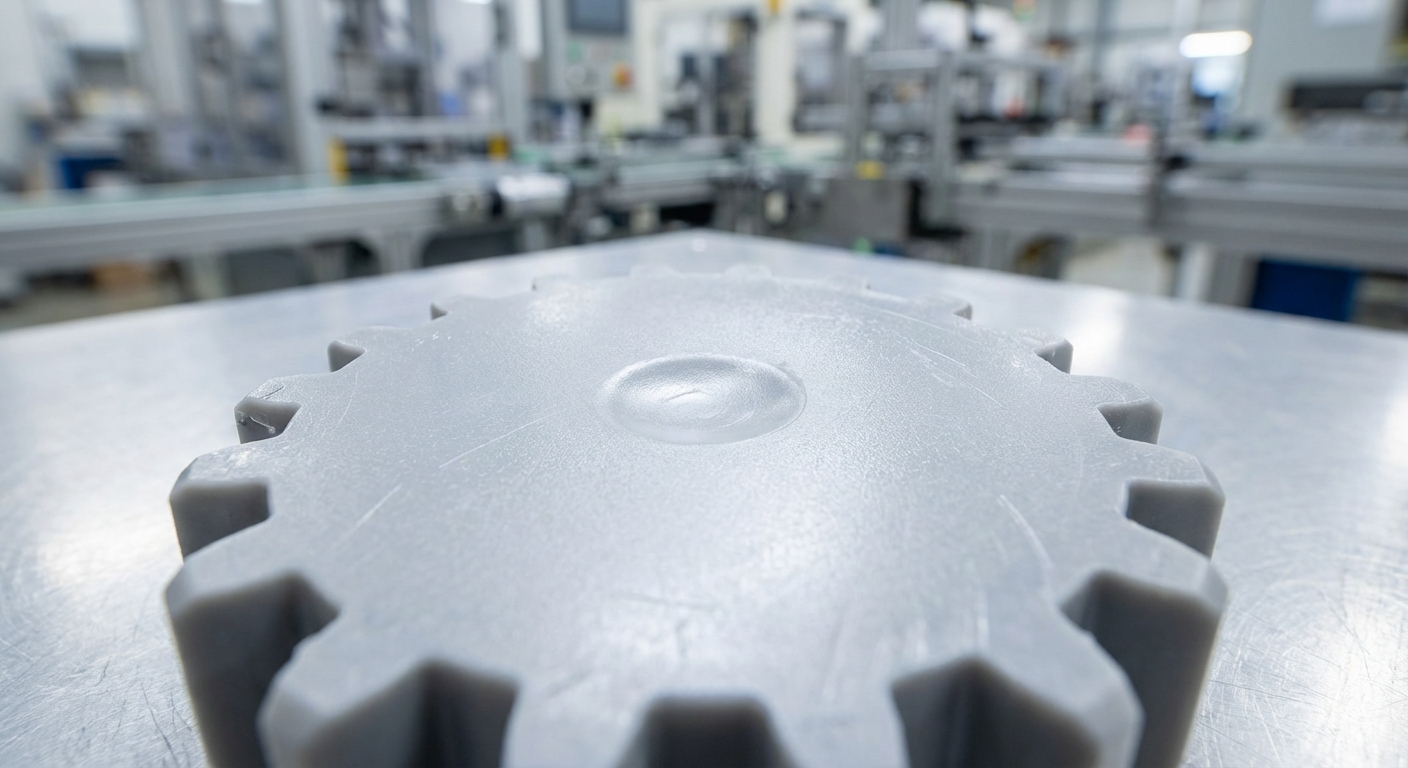
Bosses act as cylindrical heat reservoirs that frequently trigger sink marks injection molding at their base. Because bosses often house screws or fasteners, they require a certain amount of mass, which unfortunately leads to slower cooling cycles. Without careful design, the exterior side of the part will show a circular depression exactly where the boss is located.
Why is the boss base a common failure point?
The base of a boss is the point where the most material is concentrated, especially if it is not properly cored out. This concentration creates a localized “thick spot” that resists cooling and creates significant internal pull during solidification.
The reality is: You cannot ignore the base geometry if you want a defect-free exterior. Engineers often use “gussets” instead of solid thick bases to provide strength without the mass.
When should engineers consider thinning the boss wall?
Thinning the walls of a boss or adding a “recess” at the base can significantly reduce the volume of plastic that needs to cool. This reduces the thermal energy trapped at the intersection and allows the surface to solidify before shrinkage occurs.
- Use cored-out designs for all screw bosses.
- Keep boss wall thickness under 60% of the main wall.
- Implement a “sink trap” or thinned area around the base.
- Ensure the boss height does not exceed 2-3 times the diameter.
Key TakeawayCoring out bosses and utilizing support gussets maintains structural strength while drastically reducing localized heat retention.
| Boss Troubleshooting | Solution Strategy | Resulting Benefit | |
|---|---|---|---|
| Sink at Boss Base | Reduce base thickness | Flat exterior surface | |
| Weak Boss Threads | Increase material flow/pressure | Higher pull-out strength | |
| Long Cooling Cycles | Add internal cooling pins | Faster production speed |
Strategic boss design ensures that functional assembly points do not detract from the overall part quality.
Does gate design affect sink marks injection molding?
Gate design and location directly influence the pressure distribution required to combat sink marks injection molding . The gate must remain open long enough to allow extra material to be packed into the cavity as the part shrinks. When you choose custom injection molds with optimized gating, you ensure that the thickest sections receive maximum pressure during the critical cooling phase.
Why does gate size restrict material flow and packing?
A gate that is too small will freeze prematurely, cutting off the supply of molten plastic before the part has fully packed out. Once the gate is solid, no amount of machine pressure can compensate for the shrinkage occurring deep inside the mold cavity.
Here is the truth: Gate size is the “bottleneck” of the packing process. You must size gates based on the thickest section of the part, not the average thickness, to ensure effective pressure transmission.
How do multiple gates reduce the internal pressure drop?
On large or complex parts, a single gate may not be enough to maintain high pressure across the entire flow path. Using multiple gates reduces the distance the plastic must travel, ensuring that the “end-of-fill” areas still receive enough pressure to prevent sinking.
- Shorter flow lengths mean lower pressure drops.
- Multiple gates allow for faster cavity filling.
- Packing pressure is more uniform across the part surface.
- Multiple gates help manage thermal balance in large molds.
Key TakeawayProperly sized and positioned gates ensure that the packing pressure reaches the thickest features before solidification occurs.
| Gate Type | Best Application | Sink Prevention Capability | |
|---|---|---|---|
| Edge Gate | Standard flat parts | High (if sized correctly) | |
| Sub Gate | Automated production | Moderate (small size limits packing) | |
| Valve Gate | Large automotive parts | Excellent (precise timing control) |
Selecting the right gating strategy is essential for achieving the high-density packing required to eliminate surface dimples.
How does cooling prevent sink marks injection molding?
Advanced cooling strategies are vital for preventing sink marks injection molding by ensuring that heat is removed evenly from all part features. Standard cooling channels often leave “dead zones” where heat accumulates, leading to localized shrinkage issues. By utilizing specialized CNC Machining for mold components, you can create cooling paths that follow the exact contour of your part.
What are the benefits of conformal cooling channels?
Conformal cooling channels are designed to follow the complex 3D geometry of the part, providing uniform thermal management that standard straight-drilled lines cannot match. This technology significantly reduces hot spots and shortens cycle times while improving surface quality.
Consider this: Uniform cooling is the enemy of sink marks. When every part of the component cools at the same rate, internal stresses are minimized and the surface remains stable.
Why use beryllium copper inserts in “hot spot” areas?
Beryllium copper has a thermal conductivity much higher than standard mold steel, making it ideal for inserts in areas that are difficult to reach with water lines. These inserts “pull” heat away from thick sections and transfer it to the main cooling system.
- Beryllium copper dissipates heat 3-5 times faster than steel.
- Use inserts for deep ribs or narrow bosses.
- Inserts prevent localized mold overheating.
- Faster cooling results in higher dimensional accuracy.
Key TakeawayCombining conformal channels with high-conductivity inserts ensures that heat is efficiently removed from every square millimeter of the part.
| Cooling Material | Thermal Conductivity (W/m·K) | Best Use Case | |
|---|---|---|---|
| Standard Tool Steel (P20) | ~30 | General mold base | |
| Stainless Steel (420) | ~25 | Corrosion-resistant cavities | |
| Beryllium Copper | ~120 – 160 | Core pins and thick intersections |
Investing in high-performance cooling components pays for itself through reduced cycle times and lower defect rates.
Can venting solve sink marks injection molding issues?
Venting plays a critical role in preventing sink marks injection molding by allowing trapped air to escape as the plastic fills the cavity. If air cannot escape, it creates a pressurized cushion that prevents the molten plastic from fully “packing out” against the mold walls. Inadequate venting often mimics the appearance of sink marks or causes incomplete filling at the edges.
How does trapped air prevent complete part packing?
When air is trapped at the end of a flow path or in a deep pocket, it compresses and resists the incoming plastic pressure. This back-pressure makes it impossible for the machine to pack enough material into that area to compensate for shrinkage.
The reality is: You can have the highest packing pressure in the world, but if the air has nowhere to go, the plastic won’t fill the space. Proper venting ensures that the plastic makes full contact with the cooling surface.
What are the signs of inadequate mold venting?
Common indicators of poor venting include burn marks (dieseling), short shots, and “ghost” sink marks that appear in areas where the geometry seems fine. These defects are usually found at the very end of the material flow or in deep ribs.
- Burn marks on the part surface.
- Inconsistent part weights between shots.
- Surface dullness or “orange peel” textures.
- Visible air traps in clear or translucent parts.
Key TakeawayA well-vented mold allows the injection pressure to work effectively, ensuring every feature is densely packed and thermally stable.
| Venting Checklist | Recommended Spec | Critical Impact | |
|---|---|---|---|
| Vent Depth | 0.01mm – 0.03mm | Prevents flash while allowing air out | |
| Vent Width | 3.0mm – 5.0mm | Ensures sufficient volume for air escape | |
| Vent Location | End of flow / Periphery | Eliminates trapped air pockets |
Regularly cleaning and maintaining these vents is a core part of our quality control process to ensure consistent production.
What resin settings stop sink marks injection molding?
Optimizing machine settings is the final step in eliminating sink marks injection molding once the mold and part design are perfected. You must focus on the “pack-and-hold” phase, which is specifically designed to feed more material into the shrinking core. Precision control over temperature and pressure allows you to fine-tune the cooling process for the specific resin being used.
Why is the “pack-and-hold” stage critical for surface quality?
During the packing stage, the machine applies high pressure to force additional molten plastic into the cavity as the volume reduces due to cooling. This stage continues until the gate freezes, ensuring that the part is fully densified and the surface is held tight against the mold wall.
Here is the truth: If you release the pressure too early, the molten core will continue to shrink and pull the surface away from the steel. The hold time must be long enough to cover the entire solidification period of the gate.
How does melt temperature influence the gate freeze time?
Higher melt temperatures require more cooling time before the gate solidifies, which can be both a blessing and a curse. While it allows for better packing, it also increases the total heat that must be removed from the mold.
- Lower melt temps reduce the cooling burden.
- Higher melt temps improve flow and pressure transmission.
- Gate freeze occurs faster with lower mold temperatures.
- Consistent barrel temperatures prevent viscosity variations.
Key TakeawayBalancing melt temperature with extended hold times ensures the cavity remains pressurized throughout the cooling transition.
| Processing Parameter | Adjustment for Sink | Technical Goal | |
|---|---|---|---|
| Packing Pressure | Increase (5% – 10%) | Force more material into shrinkage areas | |
| Hold Time | Increase (until gate freeze) | Maintain surface contact with mold | |
| Melt Temperature | Decrease (within spec) | Reduce total thermal contraction |
Precise adjustment of these variables ensures that even the most challenging geometries meet your aesthetic standards.

Does color mask sink marks injection molding defects?
Color and surface finish can drastically change the visibility of sink marks injection molding , which is particularly important for automotive components that require high-end aesthetics. While color does not “fix” the physical defect, certain visual properties can help hide minor imperfections that are otherwise difficult to eliminate. Understanding these optical effects allows you to make smarter choices for consumer-facing parts.
Why do dark, glossy finishes make dimples more visible?
Dark colors and high-gloss surfaces act like mirrors, reflecting light in sharp, predictable paths. Any minor depression on the surface disrupts this reflection, making the sink mark stand out as a distorted highlight or a dark shadow.
Look at the facts: A glossy black part will reveal even the slightest surface variation. If your design has inherent thick sections, you should reconsider using a high-gloss finish on those areas.
How do matte textures help hide cosmetic imperfections?
Matte textures and lighter colors diffuse light in many different directions, which “hides” the shadows created by a sink mark. A textured surface breaks up the visual plane, making it much harder for the human eye to detect minor height differences.
- Textures like MT or VDI are common.
- Lighter colors (white, grey) show less shadow.
- Textured surfaces reduce the “mirror” effect.
- Proper mold etching is required for consistent texture.
Key TakeawayUtilizing textured finishes and lighter colors is a strategic way to manage the visual perception of inevitable geometric variations.
| Finish Type | Sink Visibility | Best Industry Use | |
|---|---|---|---|
| SPI-A1 (High Gloss) | Maximum | Medical, High-end Electronics | |
| SPI-C1 (Matte) | Moderate | Industrial, Hidden parts | |
| Mold-Tech Texture | Minimum | Automotive interiors, Tool housings |
Selecting the right finish allows you to deliver a professional product even when design constraints are tight.
How to eliminate sink marks injection molding permanently?
The only way to permanently eliminate sink marks injection molding is to combine rigorous DFM analysis with high-precision mold manufacturing. At CN Precision, we believe in a proactive approach that identifies potential failures before a single ounce of steel is cut. By adhering to IATF 16949 standards, we ensure that every process—from design to mass production—is optimized for zero-defect quality.
Why is an early DFM analysis the most cost-effective fix?
A Design for Manufacturing (DFM) review identifies thick sections, poor rib ratios, and suboptimal gate locations when the design is still on the screen. Changing a 3D model takes minutes; modifying a hardened steel mold takes weeks and costs thousands.
Consider this: An ounce of prevention is worth a pound of cure in the mold shop. Our engineering team provides detailed feedback to ensure your part is physically capable of being molded without defects.
How do IATF 16949 standards ensure consistent quality?
IATF 16949 certification requires a level of process control and documentation that prevents “variable” quality in mass production. It ensures that the machine settings, cooling rates, and material handling are strictly controlled shot after shot.
- Rigorous process validation for every project.
- Continuous monitoring of mold temperature and pressure.
- Strict supplier qualification for raw resins.
- Detailed inspection reports using CMM technology.
Key TakeawayPermanent elimination of sink marks requires a partnership with a manufacturer that prioritizes engineering integrity and certified quality systems.
| Quality Strategy | Reactive Troubleshooting | Proactive DFM Approach | |
|---|---|---|---|
| Cost Level | High (Mold rework/Scrap) | Low (Early design tweaks) | |
| Speed to Market | Delayed by repairs | On-time delivery | |
| Result Quality | Variable | Consistently high |
By integrating these strategies, you ensure that your production runs are efficient, profitable, and free from cosmetic blemishes.
Precision Manufacturing for Flawless Results
While sink marks are a common challenge in the plastics industry, they are entirely preventable with the right engineering expertise. By focusing on wall thickness consistency, advanced cooling, and scientific molding parameters, you can achieve a flawless surface finish on every component. At CN Precision, we specialize in high-precision mold making and automotive-grade injection molding that meets the world’s strictest quality standards.
Our brand vision is to provide a seamless bridge between complex engineering designs and high-volume manufacturing reality. We leverage over 15 years of export experience and IATF 16949 certification to ensure your projects are delivered on time, within budget, and without cosmetic defects. Don’t let surface imperfections delay your product launch or damage your brand— contact us today to discuss your project requirements with our expert engineering team.
Frequently Asked Questions
Can I use textured finishes to completely hide sink marks on thick parts?
It depends. While textures are excellent at diffusing light and masking minor surface variations, they cannot hide severe sink marks that create deep structural depressions. For the best results, you must still optimize the internal geometry to minimize the physical depth of the sink before applying a texture.
How do I calculate the maximum allowable rib thickness for my design?
Yes, the calculation is straightforward. In most cases, you should multiply the nominal wall thickness by 0.5 to find the target rib thickness. If you are using a low-shrinkage resin, you can occasionally go up to 0.6 times the wall thickness, but exceeding this will significantly increase the risk of visible marks on the opposite surface.
What is the difference between a sink mark and an internal vacuum void?
It depends on the location of the shrinkage. A sink mark is a surface depression where the outer skin pulls inward, whereas a vacuum void is an internal hole that occurs when the outer skin is strong enough to resist the pull, leaving a gap in the center of a thick section. Voids are often more dangerous as they can compromise the structural integrity of the part.
Why does increasing the holding pressure sometimes fail to fix the sink?
It is likely due to gate freeze. Once the gate has solidified, no additional pressure can reach the cavity to compensate for the shrinkage occurring in thick sections. If the gate freezes before the part’s core is solid, the sink mark will remain regardless of how much pressure the machine applies.
Are there specific high-flow resins that are less prone to sinking?
Yes. Resins with lower volumetric shrinkage rates, such as amorphous plastics (ABS, PC, or PMMA), are naturally less prone to sinking than semi-crystalline materials (PP, PE, or PA). Additionally, many material suppliers offer “low-shrink” grades specifically formulated with fillers like glass fiber or minerals to improve dimensional stability.