Mold flow analysis is a specialized computer simulation used to predict how plastic resin fills a mold cavity during the manufacturing process. You likely face significant pressure to deliver high-quality parts on tight schedules without exceeding your budget. Unfortunately, unforeseen defects and tooling errors can lead to expensive delays and frustrated stakeholders. By integrating advanced simulation into your workflow, you can eliminate guesswork and ensure your designs are optimized for manufacturing success from day one. Utilizing mold flow analysis allows you to visualize potential problems before they manifest in physical hardware.
What is mold flow analysis?
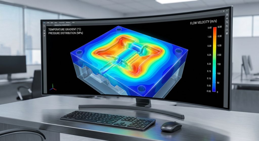
Mold flow analysis is a digital simulation tool that models the behavior of molten plastic as it is injected into a mold under specific pressures and temperatures. By using mold flow analysis , you can see a virtual representation of the entire injection cycle. This process uses finite element analysis (FEA) to calculate the flow of polymer through the gates and runners.
Simulating plastic resin flow
Think about it: you no longer have to guess how a complex geometry will fill. Simulation software uses mathematical models to track the front of the molten plastic as it moves through your part. You can observe the velocity, pressure distribution, and cooling rates in a controlled virtual environment.
- Visualizes the melt front advancement.
- Estimates the time required to fill the cavity.
- Calculates the required clamping force for the machine.
- Simulates the packing phase to ensure part density.
Identifying critical flow parameters
It gets better. Identifying the right parameters early ensures your production run stays within the required tolerances. You can adjust temperatures and pressures in the software to find the ideal processing window for your specific resin.
- Monitors melt temperature throughout the cycle.
- Determines the pressure drop across the part.
- Identifies areas of high shear stress.
- Predicts the volumetric shrinkage of the material.
Key Takeaway: Mold flow analysis provides a data-driven window into the injection process, allowing for the optimization of flow and thermal parameters before production begins.
| Parameter | Function in Simulation | |
|---|---|---|
| Melt Front | Tracks the progression of plastic into the cavity. | |
| Clamping Force | Estimates the machine tonnage required to keep the mold shut. | |
| Shear Stress | Identifies areas where material might degrade due to friction. |
The following table summarizes the primary metrics you should monitor to ensure a stable injection molding process.
When should you perform mold flow analysis?
You should perform mold flow analysis during the initial design phase, ideally before any tooling materials are ordered or cut. Implementing mold flow analysis early allows you to catch geometry-related issues while they are still easy to change. Waiting until the tool is built to find a flow issue is a recipe for project delays.
Why analyze before tool construction?
Here is the deal: steel is expensive and difficult to modify once it has been machined. By simulating early, you ensure that your gate locations and wall thicknesses are feasible for the selected material. You can provide your toolmaker with a validated design that reduces the risk of initial trial failures.
- Verifies that the part can be completely filled.
- Confirms the viability of the gate and runner design.
- Reduces the number of physical mold iterations needed.
- Ensures the cooling lines are placed effectively.
Managing design iterations early
The best part? You can iterate your design in hours rather than weeks. If the simulation shows a high risk of warping, you can modify the ribbing or wall thickness and re-run the test immediately. This rapid feedback loop keeps your project on track and ensures a smoother transition to mass production.
- Tests multiple design variations quickly.
- Provides evidence for design changes to stakeholders.
- Helps balance aesthetics with manufacturability.
- Optimizes the part for the specific molding machine.
Key Takeaway: Performing simulation during the design stage prevents costly “guess-and-check” methods and ensures the mold is right the first time.
| Development Stage | Impact of Analysis | |
|---|---|---|
| Concept Design | Identifies fundamental flow risks and geometry issues. | |
| Tooling Design | Validates gate placement and cooling channel efficiency. | |
| Pre-Production | Optimizes machine settings for the first shot. |
This timeline demonstrates how early intervention through simulation creates a more predictable manufacturing path.
Why is mold flow analysis vital for production?
Mold flow analysis is vital because it directly influences the repeatability and long-term stability of your manufacturing process. Using mold flow analysis ensures that every cycle produces a part that meets your strict quality standards. Without this data, you risk inconsistent parts that can lead to high scrap rates and customer returns.
Maximizing final part quality
But there is more. High quality isn’t just about looks; it is about structural integrity and dimensional accuracy. Simulation helps you understand how the material will behave as it cools, preventing internal stresses that lead to premature part failure. You get a clearer picture of how the part will perform in its end-use environment.
- Ensures uniform part density across all sections.
- Minimizes residual stresses that cause warping.
- Improves the surface finish by optimizing fill speed.
- Maintains tight dimensional tolerances consistently.
Achieving consistent cycle times
In short: time is money. By optimizing the cooling phase through simulation, you can shave seconds off every cycle without sacrificing part quality. This consistency allows you to accurately predict production schedules and meet high-volume demands with confidence.
- Calculates the minimum necessary cooling time.
- Balances the flow in multi-cavity molds.
- Reduces the likelihood of machine downtime.
- Stabilizes the thermal profile of the mold.
Key Takeaway: Production stability relies on the predictive power of simulation to ensure consistent quality and optimized cycle efficiency.
| Production Metric | Improvement with Analysis | |
|---|---|---|
| Scrap Rate | Significantly reduced by eliminating fill issues. | |
| Cycle Time | Minimized through optimized thermal management. | |
| Part Consistency | Enhanced by stabilizing the injection pressure window. |
The data in this table highlights how simulation translates directly into improved production performance and reliability.
How does mold flow analysis reduce project costs?
Mold flow analysis reduces project costs by preventing the need for expensive “bridge” tooling and minimize the time spent on trial-and-error at the press. Implementing mold flow analysis identifies design flaws that would otherwise require high-cost steel changes after the mold is built. These savings accumulate rapidly over the lifespan of a product.
Avoiding expensive tooling rework
Think about it. Re-machining a hardened steel mold can cost thousands of dollars and add weeks to your timeline. Simulation allows you to make these corrections in a CAD environment where the cost of change is nearly zero. You can move from design to production with the peace of mind that your tool will work.
- Eliminates the need for welding or re-cutting cavities.
- Prevents the accidental destruction of mold components.
- Saves on labor costs for mold technicians.
- Reduces shipping costs for returning tools to shops.
Minimizing material waste and scrap
Here is why it matters. Every scrapped part represents wasted resin, energy, and machine time. By ensuring a perfect fill from the first shot, you maximize your material utilization and reduce your environmental footprint. This efficiency is particularly important when working with expensive, high-performance engineering resins.
- Reduces the amount of material used in runners.
- Lowers the volume of non-conforming parts.
- Optimizes the use of regrind material if applicable.
- Decreases the total energy consumption per part.
Key Takeaway: The upfront investment in simulation software or services is a fraction of the cost required to fix a faulty mold.
| Cost Category | Savings Potential | |
|---|---|---|
| Tooling Maintenance | High, by preventing over-pressurization and wear. | |
| Material Usage | Medium, by optimizing runner and gate volumes. | |
| Speed to Market | High, by reducing the number of mold trials (T1, T2). |
The following analysis shows that cost reduction is achieved by prioritizing digital validation over physical correction.
Can mold flow analysis predict part defects?
Yes, mold flow analysis can accurately predict common defects like air traps, sink marks, and short shots before the mold is even manufactured. By leveraging mold flow analysis , you can visualize where gas might get trapped or where the plastic might cool too quickly. This predictive capability allows you to adjust the design or the venting strategy to ensure a defect-free part.
Identifying short shots and air traps
Believe it or not, these are some of the most frustrating issues to solve on the factory floor. Simulation identifies areas where the injection pressure is insufficient to fill the cavity entirely. You can also see where the air will be pushed, allowing you to place vents in the exact locations they are needed.
- Maps out the “last to fill” areas of the part.
- Highlights regions where air is likely to be trapped.
- Simulates the effect of different injection speeds on filling.
- Predicts the pressure required to avoid incomplete parts.
Predicting weld lines and sink marks
It gets better. Weld lines and sink marks can ruin the aesthetics and strength of your part. Mold flow software shows you exactly where the melt fronts will meet and where thick sections will cause surface depressions. You can then move gates or change wall thicknesses to hide or eliminate these blemishes.
- Displays the location and angle of weld line formation.
- Estimates the depth and visibility of potential sink marks.
- Allows for the optimization of packing pressure to reduce sink.
- Helps move visual defects to non-critical surfaces.
Key Takeaway: Predicting defects digitally allows you to solve quality issues before they ever reach the physical world, ensuring a high-yield production run.
| Defect Type | Simulation Indicator | |
|---|---|---|
| Short Shot | Incomplete fill at the end of the simulation. | |
| Sink Mark | Volumetric shrinkage in localized thick regions. | |
| Weld Line | Meeting of two or more melt fronts in the flow. |
Reviewing these defect indicators helps you refine your part geometry to meet both aesthetic and functional requirements.
Does mold flow analysis optimize gate locations?
Mold flow analysis optimizes gate locations by determining the most balanced path for the resin to fill the mold cavity. Correct gate placement is essential for ensuring that the part fills evenly and that the pressure is distributed appropriately. Without the insight provided by mold flow analysis, you might place a gate in a location that causes warping or structural weakness.
Strategic gate placement for balance
Think about it: an unbalanced fill can cause the mold to shift or parts to vary in dimensions. Simulation allows you to test different gate positions to find the one that results in the most uniform fill time. This balance is critical for multi-cavity tools where every part must be identical.
- Determines the best entry point for the molten resin.
- Reduces the distance the plastic must travel.
- Ensures the most critical features fill first.
- Balances the pressure between multiple gates.
Designing efficient runner systems
Here is the deal. The runner system carries material from the machine to your part, and its design impacts both cost and quality. Mold flow analysis helps you size these runners so they don’t freeze too early or waste excessive amounts of material. You can design a system that delivers the resin efficiently while remaining easy to remove.
- Optimizes runner diameter for pressure maintenance.
- Reduces material waste in cold runner systems.
- Validates the performance of hot runner manifolds.
- Minimizes the “pressure drop” from nozzle to gate.
Key Takeaway: Optimizing the delivery system through simulation ensures a balanced fill and minimizes material waste in the runner.
| Component | Optimization Goal | |
|---|---|---|
| Gate Size | Balanced to allow proper packing without freezing too fast. | |
| Runner Layout | Symmetrically designed to ensure equal flow to all cavities. | |
| Gate Location | Positioned to minimize weld lines and air traps. |
These optimization goals ensure that your delivery system supports a stable and efficient injection molding process.

How do materials impact mold flow analysis?
Materials have a profound impact on mold flow analysis because every resin has unique viscosity, thermal, and shrinkage characteristics. Using mold flow analysis allows you to plug in specific material data to see how it will behave in your specific geometry. Different plastics require different processing conditions, and simulation helps you find the right ones for your chosen resin.
Evaluating resin viscosity and pressure
But there is more. Some resins flow like water, while others are as thick as molasses. Simulation software includes extensive databases of material properties that account for how viscosity changes with temperature and shear rate. This data is vital for predicting whether your part will fill correctly or if it will require excessive pressure.
- Accounts for the non-Newtonian behavior of polymers.
- Predicts how glass fibers or fillers affect flow.
- Identifies the risk of material degradation at high shear.
- Evaluates the effect of regrind ratios on flow.
How does thermal performance affect flow?
In short: heat is everything. The rate at which a material absorbs and releases heat determines how long the cycle will take and how the part will shrink. Mold flow analysis models the thermal exchange between the plastic and the mold steel, providing a highly accurate prediction of cooling behavior.
- Simulates the cooling rate based on material thermal conductivity.
- Predicts how quickly the gate will freeze off.
- Identifies “hot spots” in the mold that delay the cycle.
- Calculates the ejection temperature for safe part removal.
Key Takeaway: Accurate material data is the foundation of a reliable simulation, allowing for precise predictions of flow and cooling behavior.
| Material Property | Influence on Molding | |
|---|---|---|
| Melt Flow Index | Determines how easily the material fills the cavity. | |
| Specific Heat | Impacts the amount of cooling energy required. | |
| Shrinkage Rate | Dictates the final dimensions of the molded part. |
Understanding these material properties through simulation allows you to select the best resin for your application and mold design.
Is mold flow analysis used for rapid tooling?
Yes, mold flow analysis is increasingly used for rapid tooling to validate designs that use 3D printed mold inserts or soft metal alloys. While traditional steel tools are forgiving, rapid tooling often has different thermal properties that must be accounted for. Simulation ensures that these non-traditional molds can withstand the heat and pressure of the injection process.
Validating 3D printed mold designs
Here is why it matters. 3D printed molds often have lower thermal conductivity than tool steel. Mold flow analysis allows you to simulate how heat builds up in these inserts and whether they will require longer cooling times or specialized cooling channels. This prevents the mold from failing prematurely during a short production run.
- Tests the thermal limits of polymer-based mold inserts.
- Optimizes cooling for 3D printed conformal channels.
- Predicts the life expectancy of the rapid tool.
- Identifies areas where the mold might deform under pressure.
Thermal simulation for polymer inserts
The best part? You can use simulation to find the exact “sweet spot” for your cycle times with rapid tooling. Because these materials behave differently than steel, the standard rules of thumb often don’t apply. Simulation provides the custom data you need to successfully use these innovative tooling methods.
- Adjusts the injection speed to manage mold temperature.
- Validates the use of inserts for complex internal features.
- Compares different rapid tooling materials side-by-side.
- Reduces the risk of melting or warping the mold itself.
Key Takeaway: Simulation is essential for rapid tooling to compensate for the different thermal and mechanical properties of non-steel mold materials.
| Tooling Type | Key Simulation Focus | |
|---|---|---|
| 3D Printed Inserts | Heat dissipation and structural integrity under pressure. | |
| Soft Aluminum Tooling | Wear patterns and thermal cycle stability. | |
| Bridge Tooling | Balancing speed of production with part quality. |
This comparison shows how simulation must be tailored to the specific type of tooling technology being utilized.
How does mold flow analysis support DFM?
Mold flow analysis supports Design for Manufacturing (DFM) by providing empirical data that validates or challenges your design choices. By incorporating mold flow analysis into your DFM process, you move beyond generic guidelines and into part-specific optimization. This data-driven approach ensures that your design is not just “manufacturable” but truly optimized for high-yield production.
Enhancing part manufacturability
Think about it. A DFM report might suggest a thinner wall, but a simulation will prove exactly how that change affects the fill pressure and part strength. This level of detail allows you to push the boundaries of design while maintaining a high degree of confidence in the final outcome. It turns “should work” into “will work.”
- Provides quantitative evidence for design modifications.
- Identifies thin sections that may cause flow hesitation.
- Validates the necessity of draft angles for ejection.
- Optimizes rib-to-wall thickness ratios to prevent sink.
Making data-driven design decisions
It gets better. Instead of arguing over design preferences, your team can look at the simulation results and make decisions based on facts. This reduces the friction between design engineers and manufacturing teams, as everyone can see the impact of design choices on the final product’s quality and cost.
- Simplifies communication between design and production.
- Documents the reasoning behind specific design features.
- Provides a baseline for future design iterations.
- Increases the “right-first-time” rate for new products.
Key Takeaway: Simulation transforms DFM from a set of static rules into a dynamic, part-specific optimization process.
| DFM Principle | Simulation Validation | |
|---|---|---|
| Uniform Wall Thickness | Proven by even cooling and pressure distribution maps. | |
| Gate Location | Validated by balanced fill patterns and weld line locations. | |
| Rib Design | Confirmed by the absence of sink marks in visual reports. |
The integration of simulation into your DFM workflow ensures that every design choice is backed by solid manufacturing data.

How to start using mold flow analysis today?
You can start using mold flow analysis today by either investing in simulation software or partnering with a manufacturing provider who offers these services. Choosing the right path depends on your internal capabilities and the frequency of your injection molding projects. For most companies, the quickest way to get results is to work with experts who can interpret the data and provide actionable recommendations.
Selecting the right simulation software
Here is the deal. There are many software options available, ranging from basic CAD plug-ins to high-end, standalone FEA solvers. You need to select a tool that matches the complexity of your parts and the level of precision your industry requires. High-precision medical or aerospace parts often demand the most advanced simulation capabilities.
- Evaluates software based on its material database size.
- Considers the ease of integration with your existing CAD tools.
- Look for solvers that can handle complex multi-shot or insert molding.
- Assess the level of technical support provided by the software vendor.
Working with manufacturing experts
The best part? You don’t have to be a simulation expert to benefit from the technology. Professional manufacturing partners can run the analysis for you and provide a detailed report with specific suggestions for design improvements. This allows you to focus on your product design while they handle the complexities of manufacturing physics.
- Gains access to high-end software without the capital investment.
- Receives expert interpretation of complex flow data.
- Shortens the learning curve for your engineering team.
- Ensures the simulation matches real-world machine capabilities.
Key Takeaway: Whether through software or partnerships, starting with simulation today will immediately improve your manufacturing outcomes and reduce project risk.
| Implementation Path | Pros | Cons | |
|---|---|---|---|
| In-House Software | Full control and immediate iteration. | High initial cost and training time. | |
| Expert Partnerships | Low cost and professional insights. | Reliance on external schedules. | |
| Hybrid Approach | Speed for simple parts, expertise for complex ones. | Requires managing two workflows. |
Choosing the right implementation strategy will allow you to leverage the full power of simulation for your specific business needs.
The complexity of modern injection molding requires a move away from traditional trial-and-error methods toward a more predictive, data-driven approach. Mold flow analysis solves the critical problem of manufacturing uncertainty by providing a digital twin of your injection process. By identifying defects, optimizing gates, and validating materials before production, you ensure that your products hit the market faster and at a lower cost. As the industry moves toward smarter, more automated factories, those who embrace these simulation tools will hold a significant competitive advantage. Take the next step in optimizing your production process and contact us today to see how expert-led simulation can transform your manufacturing results.
FAQ
Can I use mold flow analysis for any material?Yes, as long as the material’s characterization data—such as its viscosity, thermal conductivity, and PVT data—is available in the software’s library. Most major resin manufacturers provide this data to software vendors, and for custom blends, you can often have the material professionally tested and modeled.
What’s the best time to start simulation?The best time is during the preliminary design phase before any tooling commitments are made. Starting early allows you to adjust wall thicknesses, rib locations, and gate positions without the high cost of modifying a physical mold, ensuring the design is truly optimized for the injection process.
How do I know if the results are accurate?You can confirm the accuracy by comparing the simulation’s predicted fill patterns and pressure drops against the actual results of the first mold trials. While modern software is highly precise, the quality of the output depends on the accuracy of the input data, including material properties and machine settings.
Can I reduce my cycle time with this?Absolutely, because the software allows you to optimize the cooling layout and packing phase to their absolute limits. By identifying “hot spots” and reducing the necessary cooling time to reach ejection temperature, you can often shave significant time off every cycle while maintaining part quality.
What’s the best software for high-precision parts?Specialized, standalone finite element analysis (FEA) solvers are generally the best choice for high-precision or safety-critical components. These tools provide deeper insights into complex physics, such as fiber orientation, crystallinity, and residual stress, which are essential for meeting tight tolerances and structural requirements.