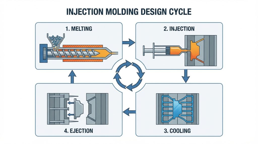
Designing molded parts requires a deep understanding of material flow, cooling dynamics, and mechanical constraints to ensure parts can be ejected reliably and repeatedly. You face the constant pressure of tight production timelines and the fear of costly tool re-designs. Overlooking small details in the early stages can lead to warping, sink marks, or even catastrophic tool failure during the first run. By mastering injection molding design , you can streamline your manufacturing process and achieve high-quality results from the very first shot.
Why is injection molding design important?
Robust design ensures your parts are manufacturable, cost-effective, and aesthetically pleasing. When you prioritize the fundamentals, you eliminate the risk of “unmoldable” geometry that forces expensive last-minute changes. Successful injection molding design acts as the bridge between a digital concept and a physical product that performs reliably in the field.
You have to consider that every feature you draw in CAD must eventually be mirrored in a steel or aluminum tool. If the design is too complex, the mold becomes difficult to build and maintain. This directly impacts your bottom line and your time-to-market.
How does it improve part manufacturability?
Designing for the process means your part will fill evenly and eject without sticking. It allows the resin to reach every corner of the cavity without excessive pressure.
Here is the kicker:
- It reduces the need for secondary operations.
- It ensures consistent dimensions across high volumes.
- It prevents common defects like short shots.
Can it lower manufacturing costs?
Smart design choices minimize the amount of material used and the time the part spends inside the machine. By optimizing the cooling phase, you can shave seconds off every cycle.
But wait, there is more:
- Simplified molds require less maintenance over time.
- Lower scrap rates mean you aren’t paying for wasted resin.
- Faster cycle times lead to lower per-part costs.
Key Takeaway: Prioritizing design at the start of a project prevents technical debt and ensures a smooth transition to mass production.
| Impact Area | Benefit of Good Design | |
|---|---|---|
| Production Speed | Shorter cycle times through optimized cooling. | |
| Quality Control | Reduced occurrence of sink marks and warping. | |
| Tooling Life | Less stress on the mold during ejection. |
The following table summarizes how strategic design decisions influence the overall health of your production line and product quality.
How do draft angles impact injection molding design?
Draft angles allow the part to release from the mold surface with minimal friction and drag. Without these tapered surfaces, the cooling plastic will shrink onto the mold’s core, making it nearly impossible to remove without damage. Integrating proper draft into your injection molding design is a non-negotiable step for any professional engineer.
Typically, you should aim for at least one degree of draft for every inch of cavity depth. However, if you are using heavy textures, you might need much more to prevent “scuffing” the finish.
Why is easing part release critical?
When a part sticks, the ejector pins might push right through the plastic or deform the surface. This leads to high scrap rates and potential damage to the mold itself.
Here is the deal:
- Draft reduces the vacuum effect during mold opening.
- It prevents cosmetic “drag marks” on vertical walls.
- It allows for a more automated, hands-off production.
What are the general rules for draft?
While one degree is the standard, different materials and finishes require specific adjustments. Polished surfaces are more forgiving than matte or spark-eroded textures.
But that is not all:
- Increase draft to 3-5 degrees for heavily textured parts.
- Ensure both internal and external walls are drafted in the same direction.
- Check that draft doesn’t interfere with the part’s functional fit.
Key Takeaway: Draft is the most important “hidden” feature in a molded part that ensures mechanical success during the ejection phase.
| Feature Type | Recommended Draft Angle | |
|---|---|---|
| Smooth/Polished Walls | 0.5 to 1.0 Degrees | |
| Standard Functional Walls | 1.0 to 2.0 Degrees | |
| Textured Surfaces | 3.0 to 5.0+ Degrees |
Understanding these guidelines helps you avoid the common pitfalls of stuck parts and ruined tool finishes.
Why are radii useful in injection molding design?
Radii, or rounded corners, are useful because they eliminate sharp edges that cause stress concentration and impede plastic flow. Sharp internal corners act as “stress risers” where parts are most likely to fail under load. Incorporating radii into your injection molding design results in a part that is both stronger and easier to manufacture.
When plastic flows into a cavity, it behaves much like water in a pipe. Smooth, rounded turns allow the resin to fill the mold more naturally and with less turbulent flow.
How do radii enhance material flow?
Resin prefers a path of least resistance to avoid building up internal pressure. Rounded corners prevent the material from “bottlenecking” as it fills the mold.
Here is the kicker:
- It creates a more uniform molecular structure in the part.
- It reduces the risk of “gas traps” in sharp corners.
- It ensures the part fills completely at lower pressures.
Can radii reduce part sticking?
Rounded edges don’t “grab” the mold the way sharp 90-degree angles do. This makes the ejection process smoother and more predictable.
Believe it or not:
- It protects the delicate sharp edges of the mold steel.
- It helps the part slide off the core more easily.
- It prevents the part from cracking during the cooling phase.
Key Takeaway: Replacing sharp corners with radii is a simple way to boost part strength and improve the cosmetic finish of the final product.
| Design Feature | Effect on Part | |
|---|---|---|
| Sharp Corners | High stress, poor flow, potential failure points. | |
| Rounded Radii | Distributed stress, smooth flow, higher integrity. | |
| Filleted Ribs | Better transition from wall to support feature. |
By utilizing rounded transitions, you ensure the resin maintains its properties throughout the entire geometry of the part.
How to manage wall thickness in injection molding design?
Managing wall thickness involves maintaining a uniform dimension throughout the part to ensure even cooling and shrinkage. Inconsistent thickness leads to “sink marks” where thick sections pull the surface inward as they cool. A balanced injection molding design uses the thinnest walls possible that still meet the structural requirements of the application.
Thicker sections take much longer to cool than thin ones. This creates internal stresses that can cause the part to warp or bow after it is removed from the tool.
How do you avoid sink and warp?
Uniform walls allow the part to shrink at a consistent rate across its entire surface. If you must have a thick section, try to “core it out” to maintain a constant wall.
Here is the secret:
- Keep wall transitions gradual rather than abrupt.
- Use a wall thickness between 1.5mm and 3mm for most plastics.
- Ensure the wall is thick enough to support the resin’s flow path.
What are the resin-specific guidelines?
Different materials have different flow characteristics and shrink rates. High-flow resins can handle thinner walls, while glass-filled materials might require more girth.
But wait, there is more:
- ABS typically requires 1.1mm to 3.5mm thickness.
- Polycarbonate needs a slightly thicker range for impact strength.
- Nylon flows well but can warp if the walls are uneven.
Key Takeaway: Uniform wall thickness is the “golden rule” of molding that prevents the most common cosmetic and structural defects.
| Material Type | Typical Wall Range (Inches) | |
|---|---|---|
| ABS | 0.045 – 0.140 | |
| Polypropylene | 0.025 – 0.150 | |
| Nylon | 0.030 – 0.115 |
Maintaining these ratios will keep your scrap rate low and your customers happy with the final appearance.
Why use ribs and gussets in injection molding design?
Ribs and gussets provide structural stiffness without the need for thick, heavy walls. They allow you to maintain a thin, uniform wall while still achieving the rigidity required for mechanical loads. Effective injection molding design utilizes these features to reduce material usage and decrease cycle times.
Instead of making a whole part thick, you add thin “fins” to the back or interior. This keeps the part lightweight and prevents the sink marks associated with solid blocks of plastic.
How do ribs increase part strength?
A well-placed rib can increase the bending stiffness of a surface by several hundred percent. It acts as a structural beam that distributes force across the part.
Here is the deal:
- Ribs should be 40% to 60% of the thickness of the main wall.
- They should be spaced apart to avoid creating thick intersections.
- Height should be no more than 3 times the wall thickness.
What is the purpose of gussets?
Gussets are triangular supports that reinforce the corners where two walls meet. They prevent the walls from flexing or snapping under stress.
But that is not all:
- They help maintain the 90-degree orientation of vertical walls.
- They improve the flow of resin into standing features.
- They add significant strength to boss features and screw holes.
Key Takeaway: Ribs and gussets are the best tools for creating lightweight, high-performance parts that cool quickly and stay flat.
| Support Feature | Primary Function | Design Rule | |
|---|---|---|---|
| Structural Rib | Increases surface stiffness | 0.5x base wall thickness | |
| Corner Gusset | Reinforces wall intersections | Use 2-3 per corner for maximum stability | |
| Boss Ribs | Supports screw towers | Tapered to allow for easy ejection |
Using these features correctly allows you to engineer parts that outperform solid designs while saving on resin costs.
What is core-cavity in injection molding design?
The core-cavity approach involves splitting the part geometry between the two halves of the mold to maintain consistent wall thickness. This technique is used for hollow parts, like boxes or enclosures, where you need a “male” side (core) and a “female” side (cavity). A smart injection molding design uses core-cavity construction to simplify tooling and improve cooling.
When you use this method, the walls of your part are formed by the space between the core and the cavity. This ensures that the material is always sandwiched between two cooled metal surfaces.
How does this create parallel walls?
By drafting both the internal and external surfaces in the same direction, you create a “telescoping” effect. This allows the mold halves to meet perfectly without crashing.
Here is the kicker:
- It maintains a perfectly uniform wall throughout the depth of the part.
- It reduces the amount of metal that needs to be removed from the mold.
- It makes the cooling of deep features much more efficient.
Can it improve part cosmetics?
Since the core-cavity method avoids deep, thick ribs, it eliminates the “witness lines” and sink marks often seen on the outside of parts. The surface finish remains consistent because the plastic shrinks onto the core.
But wait, there is more:
- It allows for better venting of trapped air.
- It provides more surface area for the ejector pins to push against.
- It keeps the “show side” of the part in the cavity for a cleaner look.
Key Takeaway: The core-cavity approach is the professional standard for designing enclosures and deep-drawn plastic parts.
| Mold Side | Purpose | Cosmetic Expectation | |
|---|---|---|---|
| Cavity (A-Side) | Forms the exterior of the part | High polish or texture; “Show Side” | |
| Core (B-Side) | Forms the interior of the part | Functional finish; contains ejector pins |
This structural breakdown ensures that the most critical dimensions and aesthetic surfaces are handled by the appropriate side of the tool.
How to solve undercuts in injection molding design?
Undercuts are solved by using side-actions, lifters, or manual inserts that move out of the way before the part is ejected. An undercut is any feature that prevents the part from being pulled directly out of the mold along the “line of draw.” Successful injection molding design seeks to minimize these features, but when they are necessary, mechanical solutions are available.
Side-actions are moving parts of the mold that slide in from the side to create holes or tabs. They add complexity to the tool but allow for much more functional part designs.
How do mechanical side-actions work?
When the mold opens, an angled “cam pin” pulls the slide away from the part. This clears the undercut and allows the ejector system to do its job.
Here is the deal:
- They are great for creating side-holes or external threads.
- They must be designed to avoid crashing into other mold features.
- They usually leave a small “shut-off” line on the part surface.
Can manual inserts simplify things?
For low-volume production, a technician can place a loose piece of metal into the mold before each shot. After the part is made, it is removed by hand and the insert is popped out.
But wait, there is more:
- It significantly reduces the initial cost of the mold.
- It is ideal for internal undercuts that are hard to reach with slides.
- It increases the cycle time because of the manual labor involved.
Key Takeaway: Undercuts are manageable with the right tooling strategy, though they always increase the complexity and cost of the project.
| Undercut Type | Best Solution | Cost Impact | |
|---|---|---|---|
| External Hole | Side-Action (Slide) | High initial cost; low labor | |
| Internal Clip | Lifter or Collapsible Core | Moderate to high cost | |
| Low Volume Feature | Manual Loose Insert | Low initial cost; high labor |
Choosing the right solution depends on your budget and the total number of parts you plan to produce.
Which gates are best for injection molding design?
The best gates depend on your part’s geometry, material choice, and cosmetic requirements, with tab gates being the most common for general use. The gate is the opening through which the molten plastic enters the cavity. Optimizing gate placement in your injection molding design is crucial for ensuring the part fills completely without showing unsightly “vestiges.”
Edge gates or tab gates are easy to machine and provide a strong flow of material. However, they leave a small piece of plastic that must be trimmed off after molding.
Why use sub gates or tunnel gates?
Sub gates are designed to “self-degate” as the part is ejected from the mold. This eliminates the need for manual trimming and speeds up the production process.
Here is the kicker:
- They hide the gate mark on the side or bottom of the part.
- They are excellent for high-volume, automated runs.
- They require specific part geometry to function correctly.
What are the hot tip options?
Hot tips allow the plastic to enter the mold through a heated nozzle, leaving only a tiny “pimple” on the part. This method produces zero waste because there is no runner system to discard.
But that is not all:
- They are perfect for center-filling round or symmetrical parts.
- They provide the best control over material temperature.
- They are more expensive to set up but save money on material waste.
Key Takeaway: Gate selection is a balance between part aesthetics, manufacturing speed, and the cost of material waste.
| Gate Type | Vestige Level | Automation | |
|---|---|---|---|
| Tab/Edge Gate | High (Manual Trim) | Manual | |
| Sub/Tunnel Gate | Low (Self-trimming) | High | |
| Hot Tip | Minimal (Tiny mark) | High |
Selecting the right gate early ensures that the “entry point” of the plastic doesn’t interfere with the part’s function or beauty.
How does ejection affect injection molding design?
Ejection affects design by requiring flat, sturdy areas where pins can push the part out of the mold without deforming the plastic. If your part is too thin or doesn’t have enough draft, the ejector pins will leave deep marks or even punch through the surface. Managing ejection in your injection molding design ensures the part maintains its shape and appearance after the cycle is complete.
Ejector pins are usually located on the “B-side” or core of the mold. You must plan their placement so they don’t interfere with critical features or textures.
Where should pins be strategically placed?
Pins should be located at the deepest parts of the mold and near areas with high friction, like tall ribs. This provides a balanced push that prevents the part from twisting.
Here is the deal:
- Place pins on flat surfaces for a clean look.
- Use larger pins to distribute the pressure more evenly.
- Avoid placing pins on “show” surfaces whenever possible.
How do you manage gate vestige and pin marks?
Every pin leaves a slight circular mark on the plastic. You can minimize the impact by hiding these marks inside the assembly where the user won’t see them.
But wait, there is more:
- Adjust the “ejector stroke” to ensure the part clears the mold fully.
- Use “ejector blades” for thin ribs that can’t fit a round pin.
- Check for “pin push” during the cooling phase to avoid surface distortion.
Key Takeaway: Successful ejection is a dance between mechanical force and part geometry; getting it right prevents high scrap rates.
| Ejection Issue | Cause | Solution | |
|---|---|---|---|
| Pin Push / Stress | Not enough draft or cooling time | Increase draft; lengthen cycle | |
| Punch-Through | Part walls too thin | Increase wall thickness at pin location | |
| Sticking | Vacuum in mold cavity | Add air poppets or more draft |
By visualizing the ejection process, you can prevent the most frustrating mechanical failures in the production cycle.
How to evaluate an injection molding design?
Evaluating a design requires using automated software for DFM analysis followed by a manual review with an experienced applications engineer. Software can catch thin walls and missing draft, but a human specialist is essential for identifying subtle moldability issues. They provide the nuanced judgment that algorithms often miss during the initial review phase. An expert eye ensures your injection molding design is truly ready for steel.
Utilizing DFM software for initial screening
Automated tools highlight red flags like thick sections or negative draft before you commit to tooling. They save time by flagging obvious errors that would otherwise lead to production delays. Using these tools early in the CAD process streamlines the transition to manufacturing.
- Identifying inconsistent wall thickness.
- Checking for missing draft angles.
- Simulating material flow and potential air traps.
The best part: It allows you to iterate quickly without waiting for manual feedback. You can refine the geometry and resolve the most common defects at the click of a button.
Key Takeaway: Digital screening provides the foundation for a defect-free manufacturing run by catching basic geometric errors before they become expensive problems.
Consulting with manufacturing experts
A seasoned engineer looks at how the mold will actually split, move, and cool during high-volume runs. They can suggest minor tweaks that significantly reduce tooling costs and complexity. This collaborative review bridges the gap between a digital concept and a physical part.
Key Takeaway: Expert consultation adds a layer of mechanical security that software alone cannot provide, ensuring long-term tool durability.
| Evaluation Method | Primary Focus | Main Benefit | |
|---|---|---|---|
| Automated DFM | Geometric tolerances | Rapid error identification | |
| Expert Review | Tooling mechanics | Reduced production costs | |
| Flow Simulation | Resin behavior | Prevention of sink and warp |
This dual-layered evaluation approach bridges the gap between digital theory and physical manufacturing reality.
Conclusion
Mastering injection molding design eliminates the uncertainty of warping, sink marks, and costly tool re-designs. We help you transform complex concepts into high-performance parts through rigorous engineering and optimization. By focusing on uniform walls, proper draft, and strategic gating, you can achieve a seamless transition from prototype to mass production.
Our vision is to empower creators by making precision manufacturing accessible, predictable, and superior in quality for every project. Precision isn’t just a goal; it’s our standard for every shot we produce. To start your next project with confidence and receive expert guidance, contact us today for a comprehensive design review.
FAQ
How do I know if my design requires draft?Almost every molded part requires draft to ensure it can be ejected without surface damage. Without tapered walls, the cooling plastic will grip the mold core, leading to scuffs or mechanical failure.
Can I use ribs to replace thick walls?Yes, utilizing ribs is the preferred method for adding strength while maintaining thin, uniform walls. This approach prevents sink marks and reduces the overall cycle time of the part.
What’s the best way to avoid sink marks?The most effective strategy is to maintain a uniform wall thickness across the entire geometry. When thick sections are unavoidable, they should be cored out or supported by thin ribs.
Can I include internal threads in my design?Yes, internal threads can be achieved through the use of collapsible cores or unscrewing molds. While these features increase tooling complexity, they provide robust mechanical fastening options for your assembly.
How do I know if a side-action is necessary?A side-action is required whenever a feature, such as a hole or tab, is perpendicular to the direction the mold opens. If the feature blocks the part from being pulled straight out, a moving slide must be integrated.