Practical mold cooling is the strategic application of thermal management techniques to optimize cycle times and part quality in injection molding. Many facilities struggle with inconsistent part dimensions and high scrap rates due to thermal instability during production. This unpredictability eats into your profit margins and delays critical product launches for demanding global clients. By implementing a robust mold cooling strategy, you transform your production floor into a high-precision environment that consistently delivers IATF 16949 quality parts.
What defines effective and practical mold cooling?
Effective mold cooling is defined by the ability to remove heat at a rate that balances rapid cycle times with the structural integrity of the plastic part. You must look beyond simple chiller settings to analyze the actual energy transfer occurring within the tool steel. Practical mold cooling ensures that heat is extracted uniformly across the cavity to prevent localized stresses.
Achieving Thermal Balance
Think about it: If your cooling is uneven, your parts will warp as they shrink at different rates. You need to verify that your cooling channels are positioned to address the “hot spots” typically found in thick wall sections or near the gates.
Essential Cooling Metrics
- Gallons per minute (GPM) of flow.
- Pressure drop across the circuit.
- Temperature differential (Delta T) between inlet and outlet.
| Metric | Ideal Range | Impact | |
|---|---|---|---|
| Delta T | < 2°C | Uniform part shrinkage | |
| Flow Velocity | > 1.5 m/s | Turbulent heat transfer |
Correct metrics allow you to maintain a steady-state condition where the heat added by the resin matches the heat removed by the water.
Key Takeaway: Measuring your cooling performance is the only way to guarantee repeatable part quality and stable manufacturing cycles across different shifts.
Why is turbulent flow critical for mold cooling?
Turbulent flow is critical because it creates vigorous internal mixing of the fluid, which significantly improves the rate of heat transfer from the mold steel to the water. Without this chaotic movement, a stagnant boundary layer forms at the pipe wall, insulating the coolant from the heat source. Professional mold cooling systems rely on exceeding the Reynolds number of 3,000 to break this thermal resistance.

The Reynolds Number Factor
Here is the deal: You cannot simply increase pump pressure and hope for the best without understanding the fluid dynamics involved. The Reynolds number is a dimensionless value that helps you determine if your flow is laminar or turbulent based on velocity and viscosity.
- Low Reynolds Number: Laminar flow (Inefficient).
- High Reynolds Number: Turbulent flow (Efficient).
Flow Rate Requirements
| Channel Size | GPM for Turbulence (at 10°C) | GPM for Turbulence (at 40°C) | |
|---|---|---|---|
| 1/4″ | 0.45 | 0.25 | |
| 7/16″ | 0.85 | 0.45 |
Lower water temperatures require higher flow rates to achieve turbulence because the water is more viscous when cold.
Key Takeaway: Ensuring your system operates in the turbulent regime maximizes the thermal efficiency of every gallon of water pumped through your tool.
How does part thickness impact mold cooling cycles?
Part thickness impacts mold cooling by acting as a natural insulator that slows the rate at which heat can escape from the center of the plastic to the mold walls. Most unfilled resins transfer heat much slower than the tool steel, meaning the plastic itself often becomes the bottleneck in your production speed. Practical mold cooling for thick parts requires longer residence times rather than just colder water.
The Insulation Effect
But wait, there is more: The outer skin of a thick part solidifies quickly, creating a barrier that keeps the core temperature high for an extended period. If you eject the part too early, the internal heat will cause the part to warp or develop sink marks once it is out of the tool.
Critical Considerations for Thick Walls
- Use slower, steady cooling to prevent surface defects.
- Place cooling channels closer to thick ribs or bosses.
- Consider beryllium copper inserts for high-heat areas.
| Part Thickness | Cooling Time Impact | Scrap Risk | |
|---|---|---|---|
| 1.0 mm | Very Low | Low | |
| 5.0 mm | Exponentially High | High |
The relationship between thickness and cooling time is not linear; doubling the thickness can quadruple the required cooling time.
Key Takeaway: Designing your parts with uniform wall thickness is the most effective way to reduce cooling-related delays and ensure dimensional stability.
Can heat recovery systems optimize mold cooling?
Heat recovery systems can optimize mold cooling by automatically throttling water flow to maintain a specific temperature differential, allowing the mold to “self-regulate” using the heat from the resin. This approach is particularly useful when you need to run specific zones of a tool warmer than the chiller water allows at full flow. Integrating these systems into your mold cooling setup can significantly reduce energy consumption.
Throttling for Temperature Control
It gets better: By monitoring the return water temperature, these systems ensure that the mold stays at a steady-state temperature without the need for external heaters in some cases. This maintains a consistent thermal profile throughout the production run, even if the plant’s water pressure fluctuates.
Benefits of Flow Regulation
- Reduced energy costs for cooling.
- Improved part surface finish (gloss).
- Consistent dimensions across long production runs.
| Feature | Impact on Production | Efficiency Gain | |
|---|---|---|---|
| Electronic Monitoring | Real-time adjustments | High | |
| Automated Valves | Constant Delta T | Medium |
Automation removes the human error factor from the cooling process, ensuring every cycle is identical to the last.
Key Takeaway: Utilizing heat recovery and automated flow control allows you to maintain precise mold temperatures while lowering the total cost of operation.
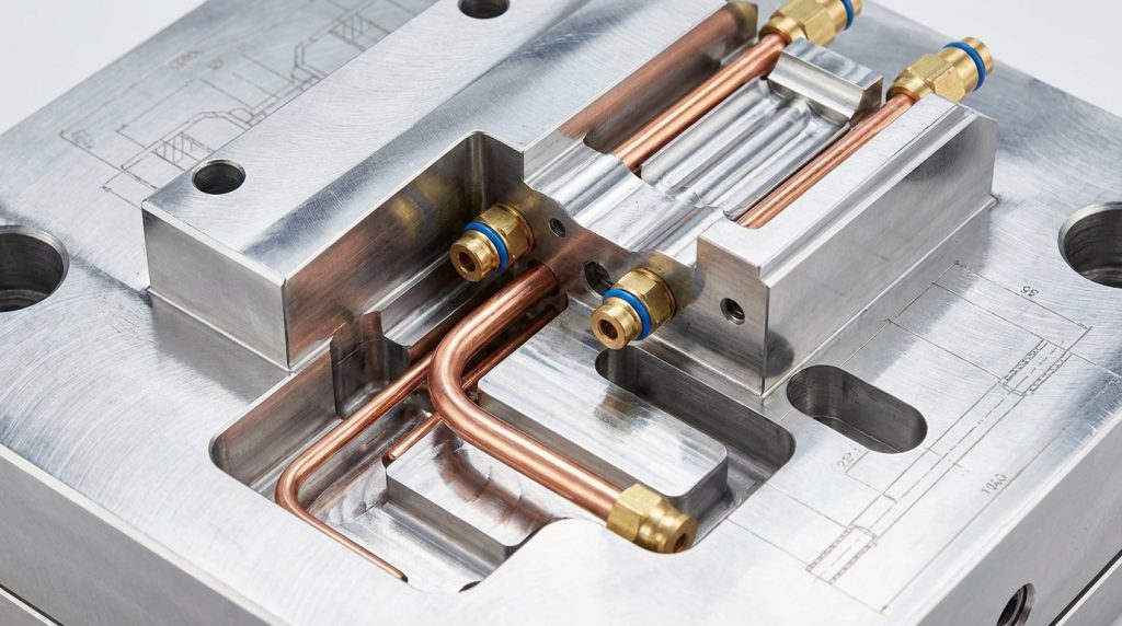
What hardware components improve mold cooling performance?
High-performance hardware components like large-diameter hoses, high-flow manifolds, and specialized quick-connect fittings improve mold cooling by reducing the overall resistance to water flow. Many shops use undersized fittings that act as bottlenecks, preventing the system from ever reaching the velocity required for turbulent flow. Upgrading your hardware ensures that your pumps can deliver the full volume of water to the tool.

Eliminating Flow Obstructions
The bottom line is this: Every 90-degree elbow and narrow fitting in your circuit creates a pressure drop that steals energy from your cooling system. You should strive for the straightest paths possible and use full-port valves to maximize the volume of water reaching the internal channels.
Recommended Hardware Upgrades
- Use 300-series quick-connects over smaller 200-series.
- Switch to high-flow water manifolds with large inlets.
- Implement smooth-bore hoses to reduce friction.
| Component | Standard Choice | High-Performance Choice | |
|---|---|---|---|
| Fittings | 1/4″ NPT | 1/2″ NPT | |
| Manifold | Small Port | Large Plenum |
High-capacity hardware is an investment that pays for itself through shorter cycle times and reduced pump wear.
Key Takeaway: Optimizing the physical connections between your chiller and your mold is a simple, cost-effective way to immediately improve cooling efficiency.
Are manifold designs essential for mold cooling efficiency?
Manifold designs are absolutely essential for mold cooling efficiency because they distribute water evenly across multiple circuits while maintaining consistent pressure and volume. A poorly designed manifold with a small inlet supplying many small outlets will cause the furthest circuits to starve for water. When you integrate high-capacity manifolds into your mold cooling infrastructure, you ensure every cavity receives equal thermal treatment.
Balancing Flow Distribution
Make no mistake: The total area of the manifold inlet should be roughly equal to or greater than the sum of all the outlet areas. If the inlet is too small, the water velocity at the first few ports will be much higher than at the end of the manifold.
Manifold Best Practices
- Use stainless steel or aluminum to prevent corrosion.
- Color-code supply and return lines for easy setup.
- Install flow meters on every return line to verify flow.
| Manifold Feature | Purpose | User Benefit | |
|---|---|---|---|
| Large Plenum | Pressure stability | Uniform Cooling | |
| Integrated Meters | Visual verification | Rapid Troubleshooting |
Properly balanced manifolds eliminate the “chasing” of temperatures that often occurs when circuits are daisy-chained together.
Key Takeaway: Investing in well-engineered manifolds is the foundation of a professional and scalable cooling strategy for multi-cavity tools.
How do you calculate flow rates for mold cooling?
You calculate flow rates for mold cooling by determining the amount of heat energy (BTUs) that must be removed per hour and then solving for the required volume of water based on its heat capacity. This calculation ensures that your cooling system is physically capable of handling the thermal load of the specific resin and cycle time you are running. Accurate calculations prevent the installation of insufficient cooling that would otherwise lead to production delays.
Determining Thermal Load
Here is the secret: You must account for the mass of the plastic injected per hour and the specific heat of that material to find the total energy input. Once you have this number, you can calculate the GPM needed to keep the temperature rise of the water within an acceptable 1°C to 2°C range.
Necessary Variables for Calculation
- Shot weight and cycle time.
- Material specific heat (e.g., PP vs. PC).
- Desired Delta T (Temperature change).
| Material | Heat to Remove (per lb) | Cooling Difficulty | |
|---|---|---|---|
| Polypropylene | High | High | |
| Polycarbonate | Medium | Medium |
Scientific calculations remove the guesswork from your cooling setup, allowing you to size your chillers and pumps correctly from the start.
Key Takeaway: Performing rigorous thermal calculations during the mold design phase ensures that your cooling system will meet production requirements on day one.
Why should you prioritize DFM for mold cooling?
Prioritizing Design for Manufacturability (DFM) for mold cooling allows you to optimize the placement and geometry of cooling channels before any steel is cut. Early DFM analysis identifies potential hot spots and interference issues that would be impossible to fix once the mold is built. Integrating mold cooling considerations into the initial design phase reduces your total tooling investment by preventing costly modifications.
Proactive Thermal Management
The reality is: Waiting until the first sample run to find a cooling problem is a recipe for disaster. Advanced simulation software can predict exactly how the heat will flow through the mold, allowing you to add baffles or bubblers exactly where they are needed most.
DFM Checklist for Cooling
- Confirm channel depth from the cavity surface.
- Check for clearance around ejector pins and lifters.
- Optimize the diameter of drilled passages for flow.
| DFM Step | Goal | Savings | |
|---|---|---|---|
| Simulation | Predict hot spots | Tooling rework costs | |
| Layout Review | Maximize coverage | Cycle time reduction |
A well-designed cooling layout is the difference between a tool that runs 24/7 and one that constantly requires maintenance.
Key Takeaway: Effective cooling starts on the computer screen; a thorough DFM review is the best insurance policy against poor mold performance.
Can water chemistry affect your mold cooling system?
Water chemistry can significantly affect your mold cooling system by causing mineral buildup or corrosion inside the cooling channels, which acts as an insulator. Scale as thin as 0.1 mm can reduce heat transfer by up to 30%, forcing you to run longer cycles to compensate for the inefficiency. Maintaining clean, treated water is essential for the long-term health of your injection molds and cooling hardware.
The Problem with Scale
But wait, there is more: Hard water contains minerals like calcium and magnesium that precipitate out of the water when it hits the hot surfaces inside the mold. This buildup not only blocks heat but also restricts flow, eventually leading to a complete blockage of small cooling circuits.
Water Quality Maintenance Tips
- Use a closed-loop system with treated distilled water.
- Regularly test pH and glycol levels to prevent corrosion.
- Implement filtration to remove particulates and biological growth.
| Issue | Cause | Effect | |
|---|---|---|---|
| Scaling | High Mineral Content | Blocked heat transfer | |
| Corrosion | Low pH / Oxidation | Internal channel damage |
Regular maintenance of your water system protects your high-precision tooling from irreversible damage and ensures consistent cooling performance.
Key Takeaway: Clean water is a prerequisite for efficient cooling; neglect your water chemistry, and your production efficiency will inevitably decline.
How do specialized materials enhance mold cooling?
Specialized materials like copper alloys or 3D-printed conformal cooling inserts enhance mold cooling by providing thermal conductivity that is far superior to standard tool steel. These materials are used in critical areas where traditional drilled holes cannot reach or where heat concentration is highest. Using high-conductivity inserts in your mold cooling strategy can shave seconds off cycles that are otherwise limited by thermal bottlenecks.
High-Conductivity Inserts
The deal is this: Beryllium copper or similar alloys can transfer heat up to ten times faster than P20 or H13 steel. By placing these materials in the cores or deep ribs of a part, you can pull heat away from the plastic much more aggressively than with water alone.
Advanced Cooling Techniques
- Beryllium copper cores and inserts.
- Conformal cooling channels via DMLS.
- Heat pipes for remote heat extraction.
| Material | Thermal Conductivity | Best Use Case | |
|---|---|---|---|
| Tool Steel | Low | Standard cavity/core | |
| Copper Alloy | High | High-heat cores/bosses |
Strategic use of materials allows you to solve the most difficult cooling challenges that traditional machining cannot address.
Key Takeaway: Combining advanced materials with traditional water cooling provides the ultimate toolkit for maximizing injection molding throughput.
Conclusion
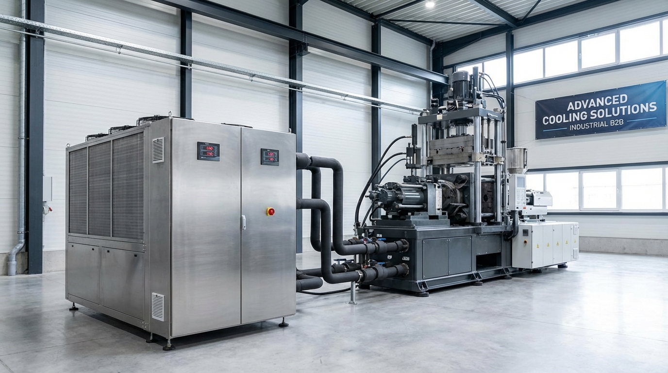
Practical mold cooling is the bridge between a theoretical design and a profitable, high-volume production reality. By mastering turbulent flow, optimizing hardware, and prioritizing thermal DFM, you solve the core problems of cycle time inefficiency and poor part quality. Our team provides the end-to-end expertise required to design, manufacture, and optimize high-precision tooling for the global market. We invite you to contact us today to discuss your next project and see how our advanced cooling solutions can elevate your manufacturing standards.
FAQ
Can I use high-flow fittings on an old mold?Absolutely. Replacing restrictive small fittings with high-flow versions is one of the fastest ways to increase water velocity and potentially reach turbulent flow.
What is the best way to detect a blocked cooling channel?Install flow meters. A sudden or gradual drop in GPM compared to the original setup is a definitive indicator of scale buildup or a physical blockage.
How do I know if my flow is turbulent?Calculate the Reynolds number. You need to know your water temperature, flow rate, and the diameter of your cooling channel to perform this calculation.
Can I run my mold without a chiller?It depends on the material and cycle time. While tower water is cheaper, it is often too warm to achieve the rapid cooling required for high-volume thermoplastic production.
How often should I clean my cooling channels?Every six to twelve months. Regular preventative maintenance with a mild descaling agent prevents the permanent loss of cooling efficiency due to mineral buildup.