High upfront tooling costs and complex design requirements often create a significant barrier for companies moving from prototyping to mass production. You may feel overwhelmed by the technical variables that determine whether a part succeeds or fails in a high-pressure environment. The solution is mastering plastic injection molding , a premier manufacturing process that injects molten resin into precision-machined steel or aluminum tools to produce thousands of identical, high-quality components.
Why is uniform wall thickness critical in molding?
Maintaining uniform wall thickness is essential because it ensures that the resin cools at a consistent rate, preventing internal stresses and surface defects. When you design parts for plastic injection molding , non-uniform walls can lead to uneven shrinkage. This variation often results in warping or the formation of unsightly sink marks on the part’s exterior.
Preventing Sink Marks
Your design must avoid thick sections that retain heat longer than the surrounding geometry.
- Nominal wall consistency
- Cooling rate balance
- Material flow speed Look: This is the first step toward aesthetic perfection.
Thick areas pull the surface material inward as the core cools, creating physical depressions.
- Rib-to-wall ratios
- Boss thickness limits
- Avoidance of clumps Think about it.
Managing Cooling Stress
Uneven cooling creates internal tension that can cause the part to twist or bow after it leaves the mold.
- Warping prevention
- Dimensional stability
- Cycle time reduction The best part? It also saves you money on production time.
Key Takeaway: Uniform walls are the foundation of structural integrity and visual quality in any molded component.
| Feature | Recommended Standard | Impact of Deviation | |
|---|---|---|---|
| Wall Thickness | 1.5mm – 3mm (Avg) | Sink marks or voids | |
| Thickness Variation | Max 25% change | Warping and stress |
Below is an analysis of how geometry affects the thermal behavior of resins.
How do core-cavity designs enhance part quality?
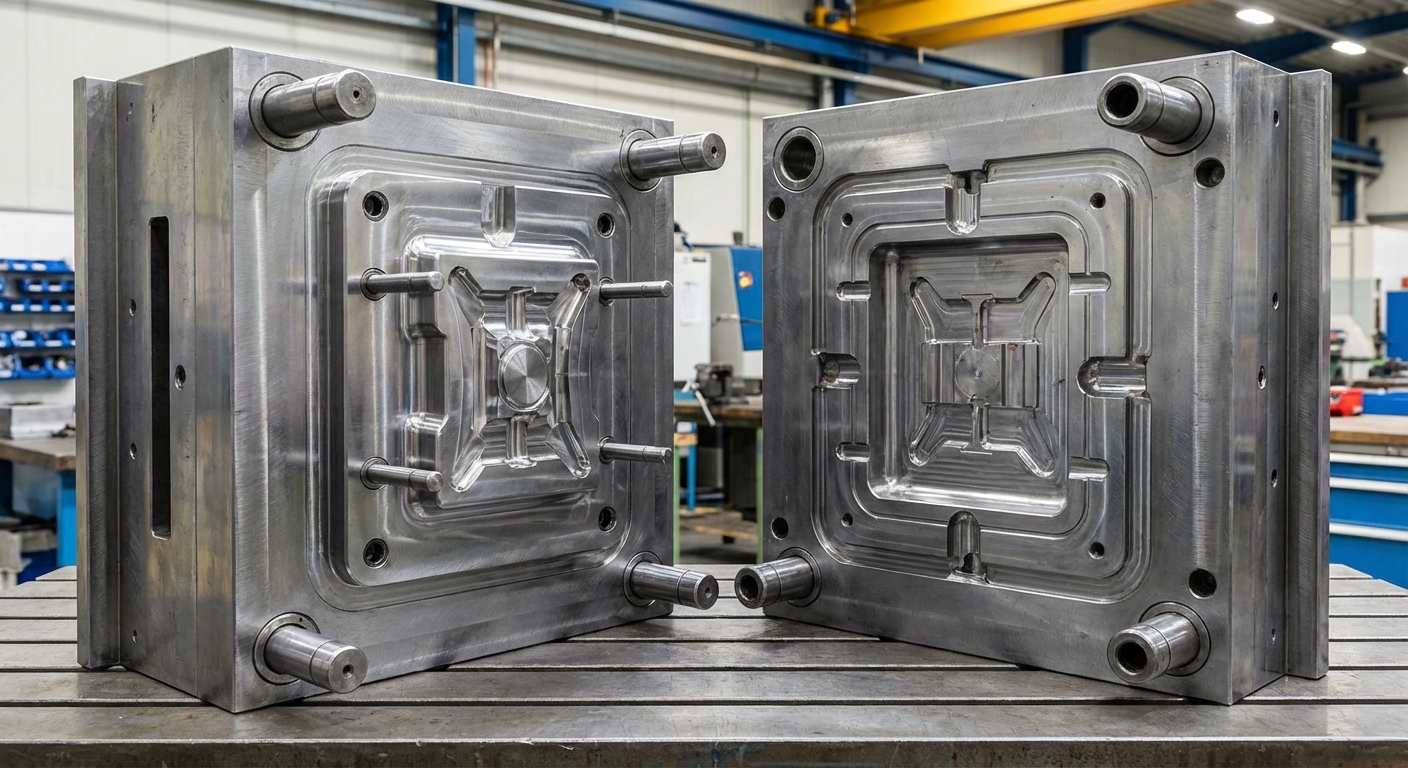
Core-cavity designs enhance part quality by providing a clear “A-side” for cosmetics and a “B-side” for structural features and ejection. This fundamental approach to plastic injection molding allows engineers to hide complex internal ribs while maintaining a smooth exterior finish. By splitting the geometry between two mold halves, you ensure the part remains seated on the ejection side during the opening cycle.
Defining Parting Lines
The parting line is where the two halves of your tool meet and determines the direction of the part’s release.
- A-side (Cosmetic)
- B-side (Mechanical)
- Flash prevention Here is the truth: A well-placed parting line is invisible to the end user.
You should collaborate with your manufacturer to place this line on a non-cosmetic edge.
- Edge placement
- Step-down design
- Alignment precision Think about it.
Balancing Mold Pressure
High-quality Injection Molds utilize core-cavity designs to distribute the clamping force evenly across the tool.
- Cavity pressure control
- Clamping force balance
- Resin flow paths The best part? This balance extends the lifespan of your expensive steel tooling.
Key Takeaway: Mastering core-cavity separation allows you to optimize both the function and the appearance of your product.
| Mold Component | Primary Function | Typical Placement | |
|---|---|---|---|
| Cavity (A-side) | Forms part exterior | Stationary side | |
| Core (B-side) | Forms part interior | Moving side |
The following data highlights the importance of mold alignment for high-tolerance production.
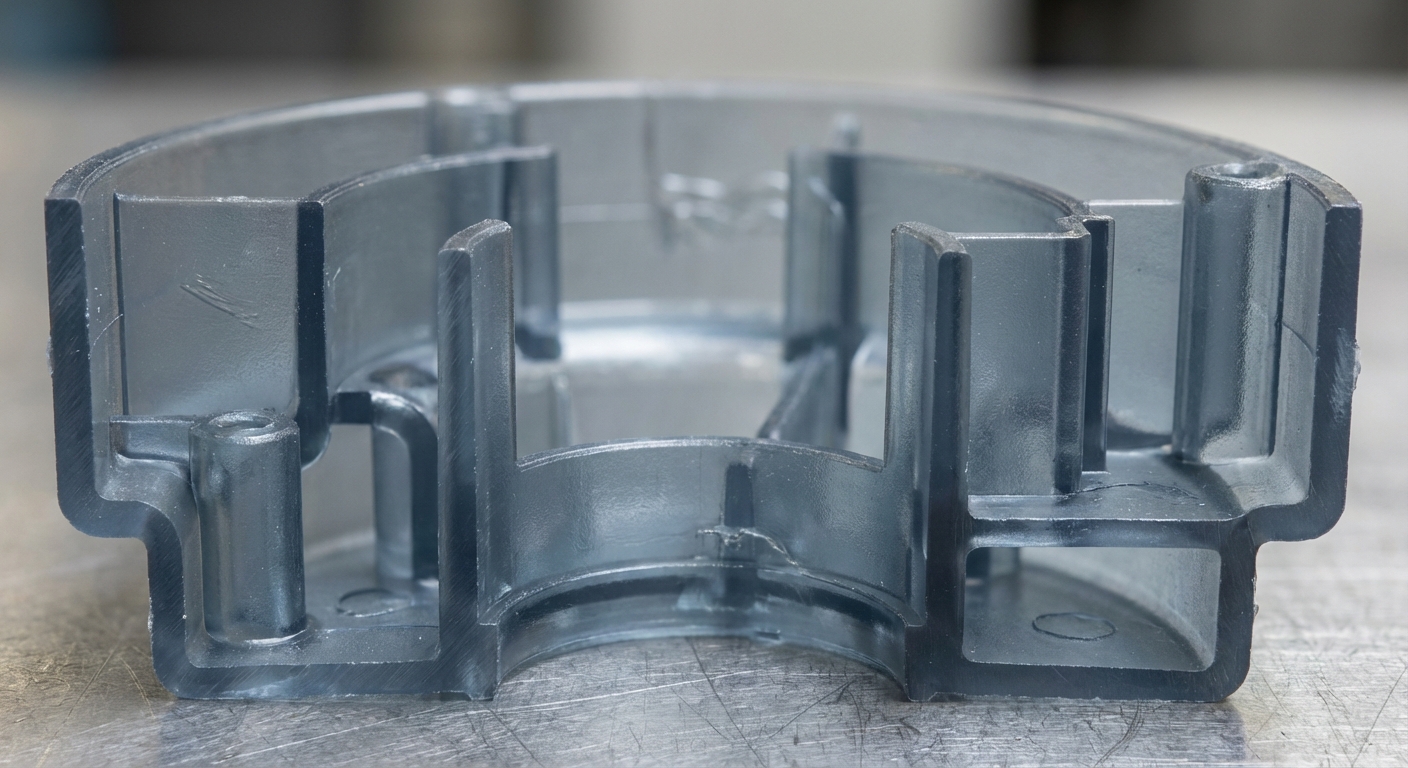
Can structural ribs and bosses prevent warping?
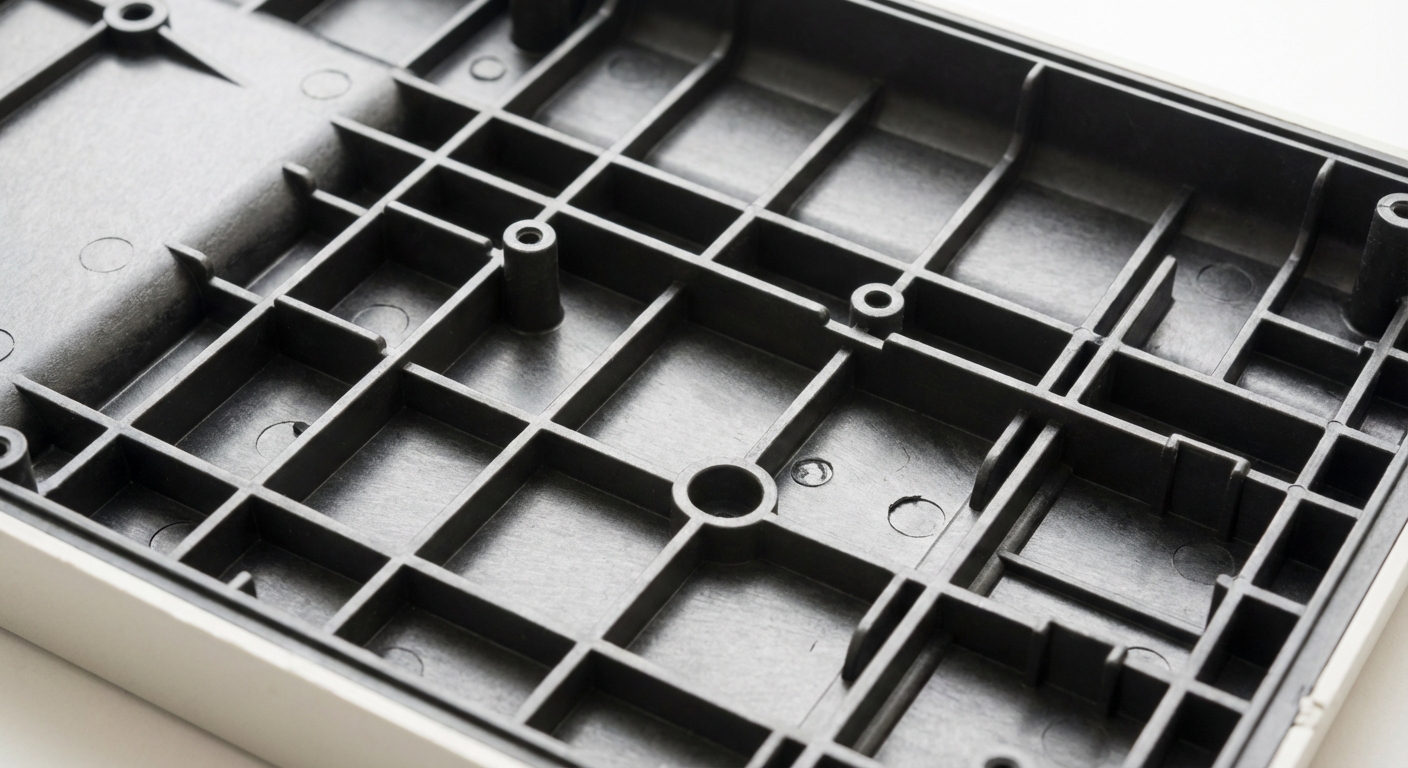
Structural ribs and bosses can effectively prevent warping by providing localized stiffness without the cooling penalties of thick walls. In the world of plastic injection molding , these features allow you to maintain a thin nominal wall while achieving the strength required for industrial applications. When designed correctly, they reinforce the part’s geometry to withstand external loads and internal stresses.
Designing Effective Ribs
Ribs should generally be between 40% and 60% of the thickness of the primary wall to avoid sink marks.
- Height-to-thickness ratio
- Spacing guidelines
- Base fillets Look: This is the secret to lightweight, rigid structures.
If your ribs are too thick, they will create the very sink marks you are trying to avoid on the cosmetic face.
- Load distribution
- Material conservation
- Bending resistance Think about it.
Implementing Secure Bosses
Bosses provide the necessary attachment points for screws or inserts without compromising the part’s overall shape.
- Screw engagement
- Gusset support
- Core-out techniques The best part? You can add significant functionality without adding significant weight.
Key Takeaway: Ribs and bosses are essential tools for adding strength while keeping your part lightweight and dimensionally stable.
| Feature | Design Rule | Purpose | |
|---|---|---|---|
| Rib Thickness | 50% of wall | Stiffness without sink | |
| Boss Height | Max 3x diameter | Ejection and stability |
Consider this breakdown of how structural features impact the mechanical performance of thin-walled parts.
Why should you avoid complex undercuts?
You should avoid complex undercuts because they prevent the part from being ejected directly from the mold, requiring expensive side-actions or lifters. While plastic injection molding is versatile, any feature that “shadows” the line of draw increases the complexity of the tool. These features significantly raise the initial investment and prolong the manufacturing cycle time.
Using Side Actions
When an undercut is unavoidable, side actions move perpendicular to the mold opening to release the trapped geometry.
- Cam-actuated slides
- Hydraulic cylinders
- Tooling maintenance Here is the truth: Complexity equals cost.
You must ensure there is enough clearance in the mold for these mechanical components to operate.
- Slide stroke distance
- Flash potential
- Mechanism wear Think about it.
Exploring Hand-Loaded Pickouts
For low-volume production, manual pickouts can be placed in the mold and removed after each shot.
- Manual intervention
- Labor cost increase
- Cycle time delay The best part? It allows for shapes that would otherwise be impossible to mold.
Key Takeaway: Minimizing undercuts simplifies your tooling and drastically reduces your per-part cost.
| Undercut Solution | Cost Impact | Production Speed | |
|---|---|---|---|
| Design Revision | Lowest | Fastest | |
| Side Action | High | Fast | |
| Hand Pickout | Medium | Slow |
This analysis illustrates the trade-offs between design complexity and total project budget.
Does a draft angle ensure smoother part ejection?
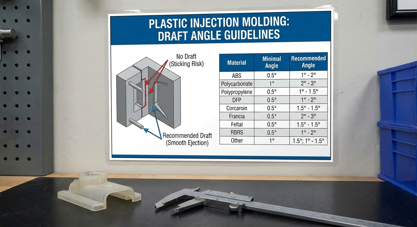
A draft angle ensures smoother part ejection by reducing the friction between the cooling plastic and the metal mold surfaces. Without sufficient draft, plastic injection molding becomes a struggle against vacuum forces and mechanical grip. A slight taper allows the part to “pop” free as soon as the mold begins to open.
Standard Angle Requirements
Most industrial parts require at least 1 to 2 degrees of draft on all vertical walls to function correctly.
- Release force reduction
- Surface finish protection
- Ejector pin efficiency Look: This is the difference between a clean part and a scrapped one.
Textures and deep ribs often require even higher draft angles to prevent dragging or scuffing.
- Texture-specific taper
- Deep cavity release
- Shrinkage compensation Think about it.
Impact on Tooling Life
Proper draft angles reduce the wear and tear on your CNC Machining Service produced tools.
- Abrasion prevention
- Cavity longevity
- Maintenance intervals The best part? Your tool will last for hundreds of thousands of additional shots.
Key Takeaway: Draft is not optional; it is a fundamental requirement for successful, high-volume manufacturing.
| Surface Type | Min Draft Angle | Recommended Draft | |
|---|---|---|---|
| Smooth/Polished | 0.5° | 1° – 2° | |
| Light Texture | 3° | 3° – 5° |
Below is a detailed look at how material-specific shrinkage affects draft requirements.
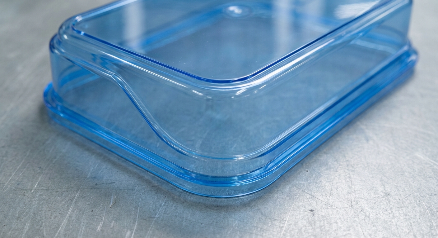
How do surface finishes impact your final product?
Surface finishes impact your final product by defining both its aesthetic appeal and its tactile functionality in the hand of the user. In plastic injection molding, the finish of the mold is directly mirrored onto the plastic part. Whether you choose a high-gloss polish or a rugged bead-blast texture, the finish must be decided early to ensure proper mold preparation.
Aesthetic vs. Functional Finishes
High-gloss finishes are ideal for transparent parts or premium consumer electronics that need to stand out.
- SPI standards
- Optical clarity
- Scratch sensitivity Look: Gloss shows every imperfection, so your design must be flawless.
Matte textures are better at hiding parting lines and minor molding defects like flow marks.
- Grip enhancement
- Fingerprint resistance
- Defect masking Think about it.
Texturing and Draft
Adding texture to a part’s surface requires you to increase your draft angles to avoid “drag marks” during ejection.
- Mold-Tech standards
- Chemical etching
- Laser texturing The best part? Texturing can make a cheap plastic part feel like a premium material.
Key Takeaway: Surface finish is a strategic choice that balances visual branding with manufacturing feasibility.
| Finish Category | SPI Grade | Common Application | |
|---|---|---|---|
| High Gloss | A-1 to A-3 | Lenses, Display screens | |
| Matte/Stone | C-1 to C-3 | Industrial housings |
This comparison shows how different finishes affect the light reflection and grip of a part.
What role do gates and runners play in flow?
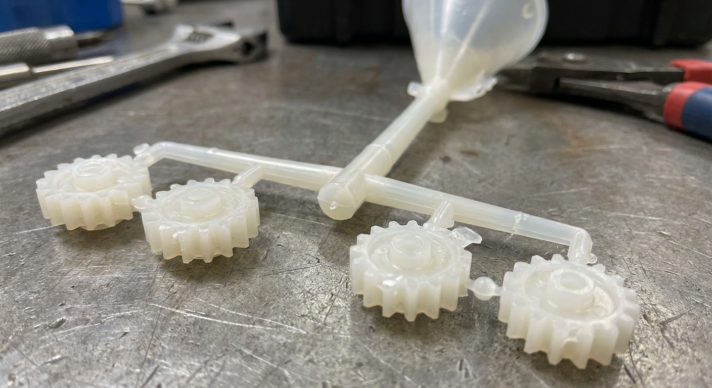
Gates and runners play the role of the delivery system, carrying molten resin from the nozzle to the individual part cavities. Efficient plastic injection molding depends on a runner system that minimizes material waste while ensuring even pressure. The gate is the specific entry point where the resin enters the part, and its location determines the final quality of the part.
Optimizing Gate Location
Placing the gate in the thickest section of the part allows the material to flow into thinner areas more easily.
- Flow path length
- Knit line placement
- Gate vestige removal Look: The gate is the “belly button” of your molded part.
You should hide the gate vestige in a non-functional or non-cosmetic area whenever possible.
- Tab gates
- Sub-gates
- Hot tip gates Think about it.
Balancing the Runner System
In multi-cavity molds, the runner must be balanced so that every part fills at exactly the same time.
- Pressure drop control
- Scrap reduction
- Cycle time optimization The best part? A balanced system prevents “short shots” and flashing across different cavities.
Key Takeaway: Proper gating and runner design are the keys to consistent part weight and structural uniformity.
| Gate Type | Vestige Level | Automation Ease | |
|---|---|---|---|
| Tab Gate | High | Manual trim | |
| Sub Gate | None | Automatic |
Explore this analysis of how runner volume impacts your total material cost.
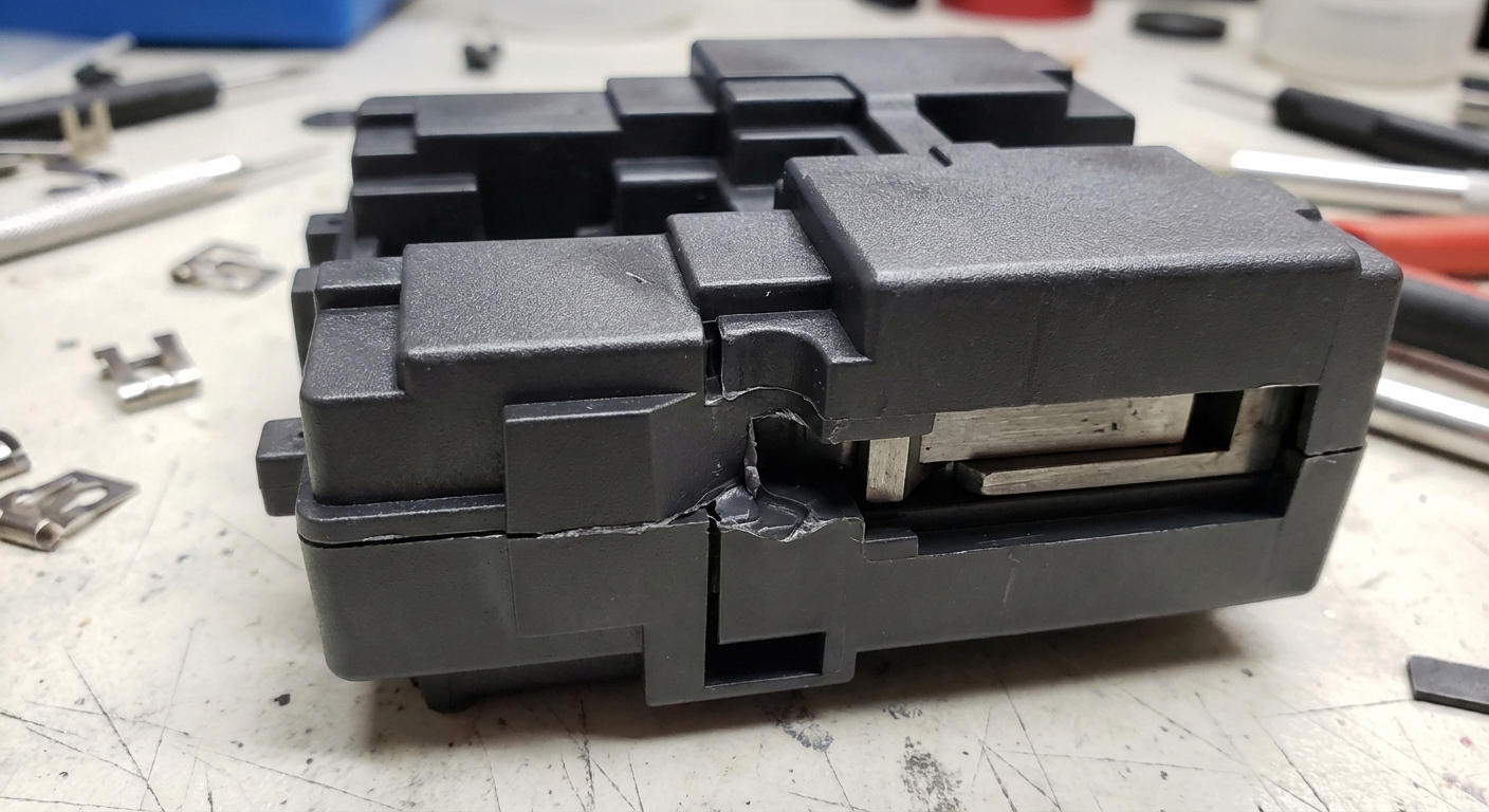
Are ejector pins the key to successful removal?
Ejector pins are the key to successful removal because they provide the mechanical force necessary to push the part out of the mold. In the final stage of plastic injection molding, these pins emerge from the B-side of the tool to overcome any remaining friction. Their placement must be carefully calculated to avoid distorting or puncturing the cooling plastic.
Pin Placement Strategies
Pins should be placed on flat, strong surfaces like internal ribs or bosses to prevent part deformation.
- Force distribution
- Pin mark visibility
- Symmetrical layout Here is the truth: If you don’t plan for pins, they will ruin your aesthetics.
You must avoid placing pins on thin cosmetic walls where they might leave permanent circular indentations.
- B-side placement
- Internal structural points
- Large surface areas Think about it.
Specialized Ejection Methods
For delicate parts, you might use stripper plates or air blasts instead of traditional pins to distribute the force.
- Stripper plates
- Pneumatic ejection
- Blade ejectors The best part? These methods ensure your part remains pristine during the most violent part of the cycle.
Key Takeaway: Ejector pins are the unsung heroes that make high-speed automation in molding possible.
| Ejection Tool | Surface Mark | Best For | |
|---|---|---|---|
| Standard Pin | Small circle | General parts | |
| Stripper Plate | None on face | Cylindrical parts |
This table outlines which ejection method is appropriate for different part geometries.
Which materials optimize plastic injection molding?
Selecting the right materials optimizes plastic injection molding by balancing performance requirements with the specific flow characteristics of the resin. Every thermoplastic has a unique “shrink rate” and “melt flow index” that affects how it fills the tool. Choosing a forgiving material like ABS can often compensate for minor design flaws that would fail in a more sensitive resin.
Choosing Engineering Resins
Engineering plastics like Polycarbonate or Nylon offer high strength and heat resistance for demanding applications.
- Tensile strength
- Impact resistance
- Thermal stability Look: Your material choice is the soul of your product’s performance.
However, these materials often require tighter control over mold temperatures and moisture levels.
- Pre-drying requirements
- Mold heating
- Tight tolerances Think about it.
Using Commodity Plastics
For cost-sensitive projects, commodity resins like Polypropylene provide excellent chemical resistance at a lower price point.
- Low cost per gram
- Living hinge capability
- Chemical inertness The best part? You can produce millions of parts with very little material overhead.
Key Takeaway: Material selection is a critical trade-off between physical properties and ease of manufacturing.
| Resin Type | Shrink Rate | Strength Level | |
|---|---|---|---|
| ABS | Low (Forgiving) | Medium | |
| Nylon (GF) | Medium | High |
Below is a comparison of how different resins behave under extreme temperature conditions.
How can you reduce total manufacturing costs?
You can reduce total manufacturing costs by optimizing your part for moldability (DFM) and selecting the right tool material for your volume. In the early stages of plastic injection molding, small design changes can eliminate the need for expensive secondary operations. By focusing on simplicity and efficiency, you ensure that your per-unit cost remains competitive as you scale.
Optimizing Tooling Material
Aluminum tools are much faster and cheaper to machine than steel, making them perfect for low-volume production.
- Machining speed
- Heat dissipation
- Lower initial cost Look: Don’t buy a Ferrari tool for a Honda production run.
If you need millions of parts, however, hardened steel tools are the only way to ensure consistency over time.
- Tooling durability
- Precision maintenance
- High-volume ROI Think about it.
Integrating Secondary Operations
Designing features like threaded inserts or snap-fits directly into the mold eliminates the need for manual assembly later.
- Snap-fit assembly
- Overmolding
- Insert molding The best part? You reduce labor costs and potential human error in your supply chain.
Key Takeaway: Cost reduction is a holistic process that starts with design and ends with smart supply chain management.
| Cost Driver | Reduction Strategy | Potential Savings | |
|---|---|---|---|
| Tooling | Use Aluminum for <10k | 30% – 50% | |
| Assembly | Use snap-fits | 15% – 25% |
This final analysis shows how a “mold-first” design philosophy maximizes your long-term profitability.
Ready to bring your product to life with precision and efficiency? Our engineering team is standing by to provide a comprehensive DFM review and help you optimize your design for mass production. Whether you need rapid prototypes or high-volume automotive components, we have the expertise and the technology to deliver results. To start your next project with a trusted manufacturing partner, contact us today for a free technical consultation.
Frequently Asked Questions
Can I use injection molding for low-volume prototyping?Yes, but it is usually more expensive than 3D printing for a single part. However, using aluminum tooling can make low-volume molding (under 1,000 parts) very cost-effective while providing production-grade materials.
What’s the best way to avoid cosmetic defects like flash?Ensure your mold is precision-machined and your clamping force is sufficient. Flash occurs when the mold halves separate slightly, allowing plastic to escape, so choosing an IATF 16949 certified manufacturer is the best way to prevent this.
How long does it typically take to get my first samples?T1 samples are usually ready within 25 to 30 days. This timeline includes the design review, mold fabrication, and the initial trial run of your parts.
Can I mold parts with different colors in the same run?Yes, but you will need to clean the machine between color changes. If you need two colors on a single part, you should look into 2K or double-injection molding processes.
What is the most common mistake for beginners in molding?Ignoring draft angles and uniform wall thickness. These two factors cause the majority of production delays and quality failures for new designers.