Visibility of seams on your molded parts can lead to high scrap rates and unexpected structural failure in the field. This frustrating defect, known as weld lines injection molding, occurs when separate flow fronts meet but fail to fuse perfectly during the filling stage. By implementing the right engineering strategies, you can minimize these marks and ensure the mechanical integrity of your components through professional plastic injection molding services.
What are weld lines in injection molding?
Weld lines are visible seams or structural weak points that form when two molten plastic fronts meet and join during the filling process. In weld lines injection molding, these features typically occur when the plastic flow must split around an obstruction, such as a core pin. If the temperature at the meeting point is too low, the molecular bond will be insufficient for high-stress applications.
Identifying visual vs structural weld lines
You must distinguish between a minor cosmetic blemish and a deep notch that compromises part strength.
- Surface lines often appear as hair-thin marks.
- Structural notches feel like a physical indentation.
- Color shifts can occur at the point of fusion.
The best part? Most cosmetic lines are acceptable for non-load-bearing components if the process is stable.
Common causes in part geometries
Part geometry is the primary driver behind the formation of these meeting fronts within the cavity.
- Internal holes or windows that divide the melt stream.
- Multiple gates that force fronts to collide.
- Significant wall thickness changes causing flow hesitation.
Think about it. If the plastic cools too much before the fronts meet, they will never truly “weld” into a single structure.
Key TakeawayUnderstanding that flow division is the root cause allows you to target geometry or process fixes effectively.
| Feature | Impact on Weld | Severity | |
|---|---|---|---|
| Core Pins | Splits flow fronts | High | |
| Thin Walls | Accelerates cooling | Medium | |
| Low Pressure | Prevents fusion | High |
This data confirms that internal obstructions are the most common source of weld-related defects in complex parts.
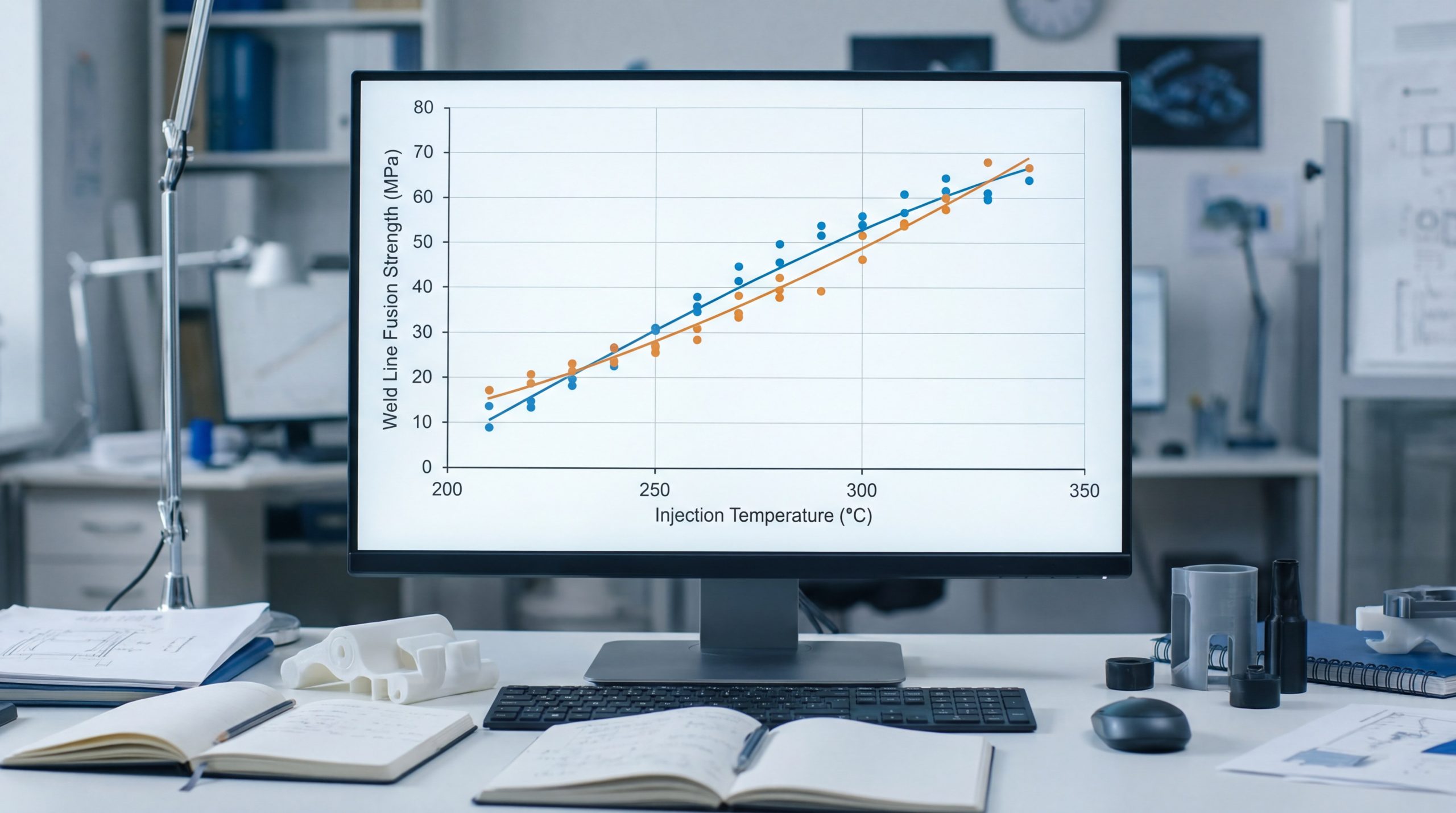
Can increasing melt temperature fix weld lines?
Increasing the temperature of the molten plastic or the mold itself improves fusion by keeping the material fluid for a longer duration. When managing weld lines injection molding, higher heat allows polymer chains to intermingle more effectively before solidification. Consistent use of weld lines injection molding thermal controls ensures a less visible seam and a stronger mechanical joint.
How mold temperature affects fusion
A warmer mold surface prevents the plastic skin from freezing too quickly as it travels through the tool.
- Reduces the thickness of the frozen layer.
- Keeps flow fronts “wet” at the contact point.
- Improves surface replication of the mold texture.
Here is the thing: While higher heat helps the weld, it also increases the overall cycle time for the production run.
Balancing heat and material stability
You cannot increase temperatures indefinitely without risking the chemical integrity of the polymer resin.
- Excessive heat causes thermal degradation.
- Burn marks or discoloration may appear.
- Flash can occur if viscosity becomes too low.
The best part? Finding the “sweet spot” ensures maximum fusion strength without sacrificing the physical properties of your material.
Key TakeawayTemperature adjustment is a powerful tool for improving fusion, provided you stay within the material’s safe window.
| Temperature Type | Effect on Weld | Potential Risk | |
|---|---|---|---|
| Melt Temp | Better molecular mixing | Degradation | |
| Mold Temp | Reduced visibility | Longer cycles | |
| Nozzle Temp | Prevents cold slugs | Stringing |
Careful monitoring of thermal parameters is essential to prevent secondary defects like warping or burning.
How does gate relocation change weld line spots?
Gate relocation moves the entry point of the plastic, which shifts the flow path and the eventual meeting point. In the study of weld lines injection molding, moving a gate is often the best way to “hide” a line in a non-visible area. By partnering with an expert for your injection molds , you can ensure the fronts join in low-stress regions.
Using DFM to predict gate positions
Modern engineering allows us to simulate the flow before any steel is cut for the production mold.
- Identifies where fronts will collide.
- Calculates pressure at the weld point.
- Allows for virtual moves to optimize appearance.
Believe it or not: A simple shift of a few millimeters in gate location can be the difference between failure and success.
Single vs multiple gate trade-offs
Adding more gates helps fill large parts but inevitably creates more meeting points for the plastic.
- Single gates eliminate multiple collision fronts.
- Multiple gates reduce required injection pressure.
- Sequential gating can “push” lines to the edges.
Let’s dive in: Managing the number of gates is a balancing act between machine limits and the aesthetic requirements of your part.
Key TakeawayGate placement is your primary tool for controlling exactly where flow fronts converge on the finished component.
| Gating Strategy | Weld Location | Structural Impact | |
|---|---|---|---|
| Single Gate | Minimized | Best | |
| Multiple Gates | Numerous | Variable | |
| Valve Gating | Controlled | Excellent |
Strategic gate placement is often the most cost-effective long-term solution for high-volume production projects.
Should you adjust wall thickness for better flow?
Adjusting wall thickness alters the speed and pressure of the plastic, directly impacting how and where fronts meet. When troubleshooting weld lines injection molding, increasing thickness in the flow path prevents the material from cooling prematurely. Properly designed weld lines injection molding paths allow the melt to reach the junction while still thermally active.
Impact of non-uniform wall thickness
When one side of a part is thicker than the other, the plastic travels at different speeds, creating a “race track” effect.
- Flow fronts may meet at weak angles.
- Thicker sections stay hot much longer.
- Abrupt changes can cause air entrapment.
Here is the secret: Uniform wall thickness is the gold standard, but strategic variations can steer the flow fronts like a rudder.
Preventing hesitation in thin sections
Thin walls cause the plastic to lose heat rapidly, which often leads to a “cold” and brittle weld.
- Increases the injection pressure needed.
- May stop the flow entirely if too narrow.
- Creates significantly weaker joints in ribs.
The reality is: If your part has thin features, you must ensure the flow fronts do not meet in those high-stress areas.
Key TakeawayWall thickness dictates the “thermal life” of the molten plastic as it fills the mold cavity.
| Thickness Change | Flow Behavior | Weld Result | |
|---|---|---|---|
| Increase | Faster, hotter flow | Stronger fusion | |
| Decrease | Slower, cooler flow | Moves weld line | |
| Variable | Uneven speeds | Angled meeting |
Designers must balance material weight savings with the need for robust flow paths that support molecular welding.
Does increasing injection speed help weld lines?
Increasing injection speed forces the plastic into the mold faster, ensuring fronts meet while at their maximum temperature. For weld lines injection molding, a faster fill reduces the time the plastic is in contact with cold mold walls. High-speed weld lines injection molding prevents the leading edge from “skinning over” before the two streams can intermix.
Managing shear heat and speed
As plastic is pushed faster through narrow channels, it generates “shear heat,” which can be beneficial for weld fusion.
- Reduces viscosity for easier flow.
- Increases temperature at the flow front.
- Helps achieve better surface replication.
Check this out: While speed is helpful, going too fast can cause “jetting” or trapped air, creating new quality issues.
Impact on air venting and gas traps
When you increase speed, the air inside the mold must escape just as quickly to avoid compression burns.
- Requires high-precision venting at the weld.
- Compressed air can prevent fronts from touching.
- Vacuum venting may be needed for high speeds.
It gets better: High-speed injection combined with excellent venting is the most effective way to eliminate the “notched” look of a seam.
Key TakeawayInjection speed is the most effective process adjustment for ensuring flow fronts meet while thermally active.
| Speed Setting | Melt Condition | Weld Appearance | |
|---|---|---|---|
| High Speed | Hot, low viscosity | Faint/Invisible | |
| Low Speed | Cool, high viscosity | Deep/Prominent | |
| Profiled Speed | Controlled fusion | Optimized |
A fast fill is generally preferred for minimizing weld line defects, provided the mold venting is adequate.
Can changing raw materials prevent weld lines?
Switching to a resin with a lower viscosity or a higher melt flow index can significantly reduce meeting front prominence. In weld lines injection molding, materials that flow easily require less pressure to fill complex geometries. Choosing a supplier who understands weld lines injection molding can help you select a resin that naturally excels at molecular interweaving.
High-flow vs low-flow resins
A resin with a high Melt Flow Index (MFI) ensures the material travels further and faster before cooling.
- Easier to fill thin-walled sections.
- Lower injection pressures required.
- Improved fusion at the meeting points.
You might be wondering: Why wouldn’t everyone just use high-flow resins? Often, they have lower mechanical strength than their low-flow counterparts.
Impact of fillers and reinforcements
Glass fibers can complicate the formation of a strong weld because the fibers do not easily cross the weld line.
- Fibers align parallel to the weld.
- Strength can drop to 50% of the base.
- Additives make the line more visible.
Here is the kicker: If your part requires structural reinforcement, you must design it so the weld lines occur in low-stress regions.
Key TakeawayMaterial properties dictate the fundamental “weldability” of the flow fronts, regardless of machine settings.
| Material Type | Flow Ease | Weld Strength | |
|---|---|---|---|
| Unfilled Amorphous | Excellent | High | |
| Semi-Crystalline | Good | Moderate | |
| Glass-Reinforced | Poor | Low |
Consulting with experts during the about us phase helps in selecting the ideal resin for your application.
Why is single source flow design effective?
A single source flow design aims to eliminate collisions by ensuring the plastic travels in one continuous direction. This technique is a premier solution for weld lines injection molding because it avoids the need for separate streams to rejoin. By optimizing your injection molds , you can create a part that is structurally continuous and aesthetically perfect.
Redesigning to avoid split flows
If a part has a window or hole that splits the flow, removing that feature from the mold can solve the issue.
- The part becomes a “solid” fill.
- Structural integrity is maximized.
- Flow front temperature remains uniform.
Think about this: It is often cheaper to add a secondary machining step than to deal with a high scrap rate from weak welds.
Moving features to the end of flow
If you cannot eliminate a hole, moving it closer to the end of the flow path can sometimes minimize the defect.
- Reduces the distance the “split” flow travels.
- Ensures higher pressure at the meeting point.
- Makes the weld line shorter and less noticeable.
The best part? A unified flow front produces the most consistent part weight and dimensional stability possible.
Key TakeawayEliminating the obstruction is the only 100% effective way to prevent a weld line from ever forming.
| Design Strategy | Flow Style | Resulting Defects | |
|---|---|---|---|
| Unified Flow | Single front | None | |
| Split Flow | Divided fronts | Potential welds | |
| Converging Flow | Multiple fronts | High risk |
Moving toward a single-flow architecture is the ultimate goal of high-performance plastic part design.
Will reducing runner dimensions improve fusion?
Reducing runner dimensions increases the velocity and shear heat of the molten plastic, which can lead to better fusion. For weld lines injection molding, smaller runners (within reason) force the material to stay hotter due to friction. Your weld lines injection molding expert will balance this carefully to avoid excessive pressure drops.
Shear thinning in small runners
As the plastic is squeezed through a tighter space, its viscosity drops significantly due to shear forces.
- Allows material to flow like a thinner liquid.
- Increases heat of the leading flow front.
- Helps in filling thin-walled part features.
Here is the truth: A well-optimized runner system acts like a pre-heater for the plastic right before it enters the part.
Balancing runner size with pressure
If the runner is too small, the machine may not be able to push the material through fast enough.
- Can lead to short shots or incomplete parts.
- Increases the cooling rate of the material.
- Can cause the weld line to form prematurely.
Let’s be clear: Runner design is a science that requires a deep understanding of fluid dynamics and polymer rheology.
Key TakeawayOptimizing runner dimensions is a subtle but effective way to control the thermal state of the plastic.
| Runner Size | Velocity | Thermal State | |
|---|---|---|---|
| Under-sized | Extremely high | Risk of burn | |
| Optimized | High | Hot and fluid | |
| Over-sized | Low | Cooler/Sluggish |
A professional mold maker will use flow simulation to determine the exact runner diameter needed for perfect fusion.
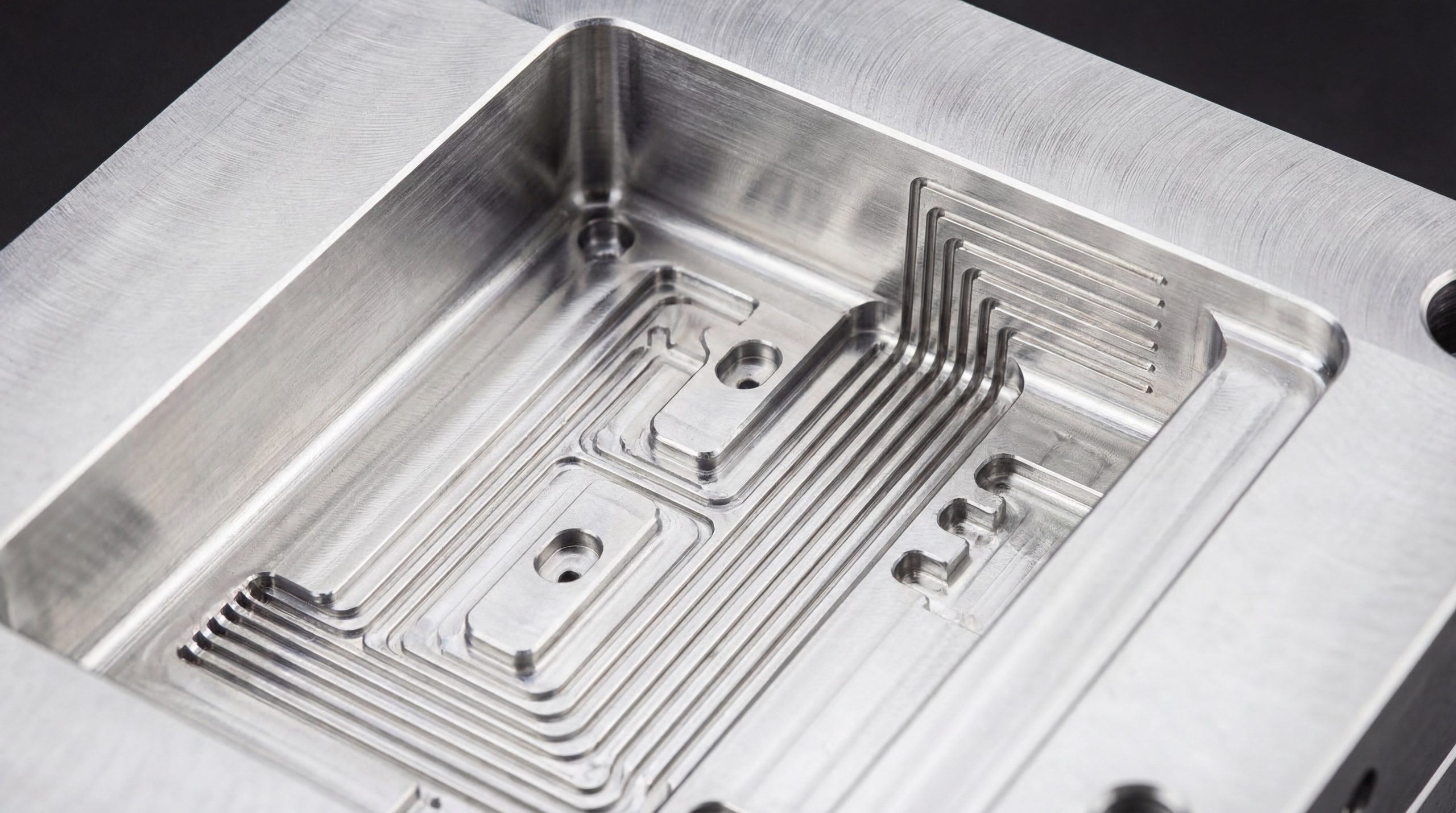
Is machining holes after molding a good idea?
Machining holes into a part after molding is a highly effective way to prevent weld lines by eliminating flow obstructions. When dealing with weld lines injection molding, the most common cause is a core pin that forces the plastic to split. By molding a solid block and using a CNC machining service , you ensure the plastic structure is continuous and strong.
Benefits of post-molding machining
While it adds a secondary step, the quality benefits for high-precision or safety-critical parts can be substantial.
- 100% elimination of weld lines around features.
- Higher dimensional accuracy for the holes.
- No risk of core pin deflection during molding.
Here is the catch: Machining adds cost and time to each part, so it is usually reserved for low-to-medium volume production.
Comparing costs: Molding vs Machining
You must weigh the cost of the secondary operation against the cost of potential scrap and mold maintenance.
- Molding holes is faster for high volumes.
- Machining is safer for critical load-bearing parts.
- Hybrid approaches (molding pilot holes) can work.
Make no mistake: If the weld line is a “deal-breaker” for your project’s success, machining is the most reliable fallback option.
Key TakeawayPost-process machining removes the physical need for the plastic to split, thereby removing the source of the weld line.
| Method | Visual Quality | Strength | Cost | |
|---|---|---|---|---|
| Molded Hole | Visible line | Lower | Lowest | |
| Machined Hole | No weld line | Highest | Higher | |
| Pilot & Ream | Minimal line | Moderate | Medium |
Evaluating these options early in the design phase prevents costly “re-tooling” later in the project lifecycle.
How does DFM analysis prevent weld line issues?
DFM analysis uses computer simulations to predict where flow fronts will meet before the mold is ever built. In the world of weld lines injection molding, DFM is the ultimate proactive tool for identifying potential failure points. By reviewing designs with a specialist in weld lines injection molding , you can fix issues in the digital realm before they become physical.
Using Moldflow to visualize fusion
Advanced software can show a color-coded map of exactly where the weld lines will appear on your part.
- Predicts front temperature at the moment of contact.
- Identifies “melding lines” (meeting at low angles).
- Allows for rapid testing of different gate locations.
Bottom line: DFM takes the guesswork out of injection molding, turning “hope” into actionable data.
Collaborative design with your manufacturer
The best results come when the part designer and the manufacturer work together during the engineering phase.
- Identifying “dead ends” in the flow path.
- Suggesting radius changes to smooth the flow.
- Optimizing cooling lines for uniform mold temperature.
Here is why it matters: An expert DFM report can reduce your total time-to-market by weeks by eliminating trial-and-error sampling phases.
Key TakeawayDFM is the most powerful preventative measure available for ensuring weld line quality in modern manufacturing.
| DFM Tool | Insight Provided | Benefit | |
|---|---|---|---|
| Flow Simulation | Meeting point location | Moves welds to hidden areas | |
| Thermal Analysis | Fusion temperature | Predicts final weld strength | |
| Pressure Map | Packing efficiency | Ensures dense, strong welds |
Investing in a thorough DFM analysis is the smartest way to ensure a smooth transition from concept to mass production.

Frequently Asked Questions
Can I eliminate weld lines entirely through process adjustments? In most cases involving core pins or multiple gates, you cannot completely eliminate the line solely through processing. However, you can make it nearly invisible and structurally sound by optimizing temperature, speed, and pressure.
What’s the best material for minimizing weld line visibility? Amorphous resins like ABS or Polycarbonate generally have better fusion properties than semi-crystalline materials like Nylon or PP, resulting in less visible lines.
How do I know if my weld line is a structural failure point? A structural defect often appears as a sharp “V” notch that can be felt with a fingernail. Destructive testing or stress simulations are the best ways to confirm mechanical integrity.
Can I move a weld line without changing the part design? Changing the gate location is the most effective way to shift a weld line’s position without altering the part’s actual geometry.
Conclusion
Addressing weld lines requires a holistic approach that spans from initial part design to final machine calibration. By implementing the nine strategies outlined—ranging from DFM analysis and gate relocation to injection speed optimization—manufacturers can produce high-quality parts that meet the most stringent standards. Whether you are producing automotive components or medical devices, understanding the fluid dynamics of your material is the key to success. For professional guidance on your next project, contact us today to start your free DFM review and optimize your production for perfect results.