Achieving undercut success requires a strategic mix of mold design, specialized tooling like side-actions, and smart material selection. You often encounter complex geometries that prevent a part from being ejected via a simple straight-pull motion, leading to design frustration and manufacturing delays. These “stuck” features can inflate production costs and compromise part integrity if you do not plan for them early. By mastering undercut injection molding , you can unlock sophisticated part designs while maintaining high efficiency and lower scrap rates.
How do you design for undercut injection molding?
Designing for success involves identifying every protrusion or cavity that sits perpendicular to the mold’s parting line. In the world of undercut injection molding, you must evaluate if a feature is absolutely necessary or if a simple design tweak can eliminate the obstruction. Many engineers find that subtle changes in orientation can turn a complex undercut into a simple straight-pull feature.
Can you simplify geometry?
You should always look for ways to minimize the number of trapped features before moving to complex tooling. Reducing the complexity of your part can lead to faster cycle times and more robust molds.
The truth is: Complex designs don’t always require complex molds if you are clever.
- Assess the functional necessity of the undercut.
- Check if a pass-through core can create the feature.
- Look for ways to merge features into the main body.
Key Takeaway: Simplifying your part geometry early reduces the reliance on expensive mechanical mold components and improves overall part reliability.
| Design Strategy | Impact on Cost | Manufacturing Complexity | |
|---|---|---|---|
| Feature Elimination | Very Low | Low | |
| Geometry Simplification | Low | Medium | |
| Tooling Workarounds | High | High |
Simplifying initial designs creates a smoother path for high-volume production stages.
Can parting lines simplify undercut injection molding?
Adjusting the parting line allows you to place undercuts along the intersection of the mold halves so they no longer “trap” the part. When you utilize the parting line for undercut injection molding , you essentially turn a side-action requirement into a standard mold opening movement. This is often the most cost-effective way to handle external features like bosses or standoffs.
Where should you place the line?
You need to analyze the part’s silhouette to determine the most logical split point that captures the most features. Zig-zagging the parting line can occasionally capture multiple undercuts across different planes.
Think about it: A well-placed line saves you thousands in tooling costs.
- Align the parting line with the widest part of the feature.
- Ensure the draft angles work in both directions from the line.
- Avoid placing the line on critical cosmetic surfaces.
Key Takeaway: Strategic parting line placement is the “low-hanging fruit” of mold design, offering a mechanical solution without the need for moving parts.
| Parting Line Type | Best Use Case | Benefit | |
|---|---|---|---|
| Flat Line | Simple symmetric parts | Lowest cost | |
| Stepped/Zig-zag | Offset features | Eliminates side cams | |
| Contoured | Complex surfaces | Follows part geometry |
Moving the parting line remains the primary method for reducing mold complexity in B2B manufacturing.
Are side-actions key for undercut injection molding?
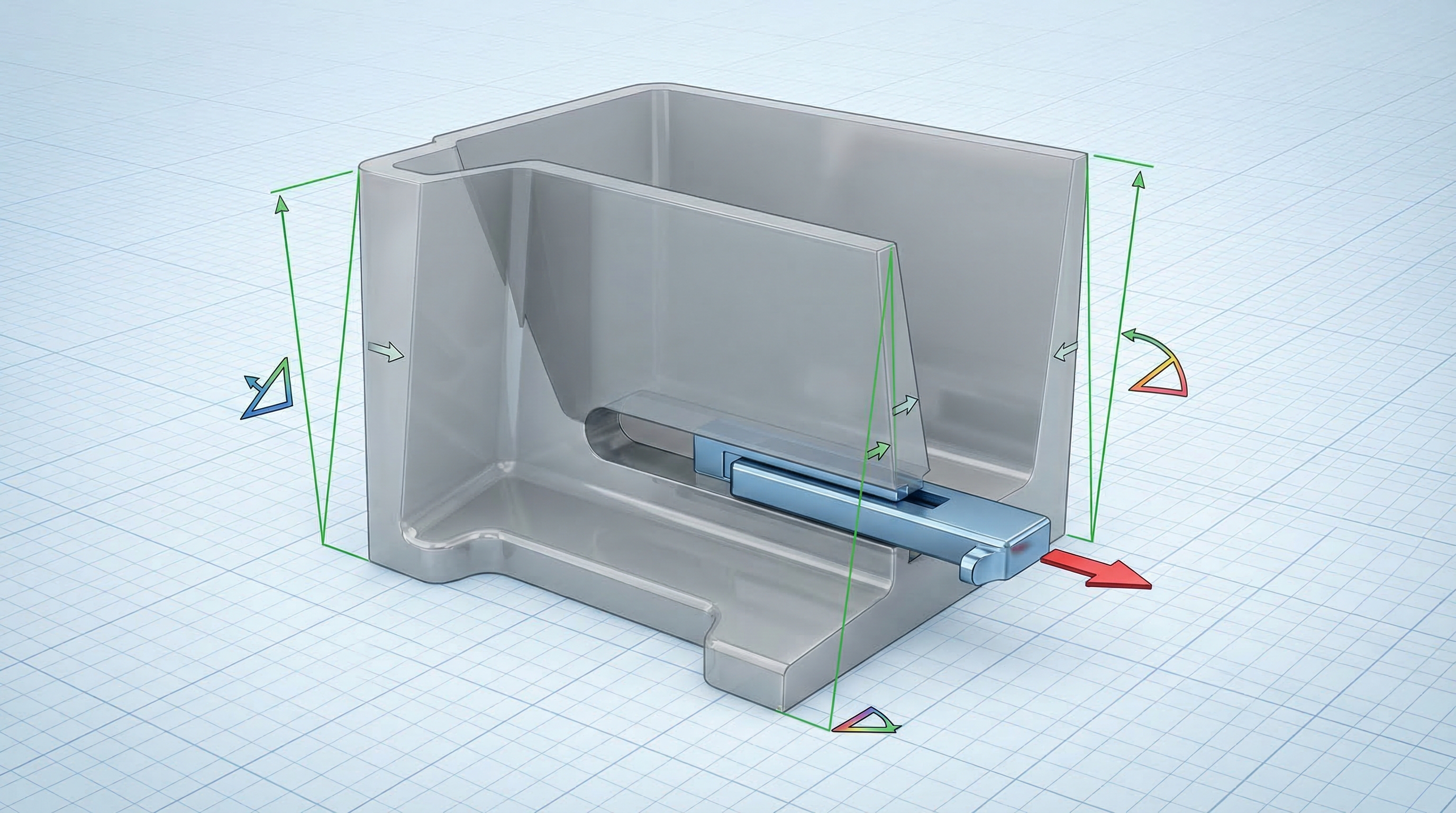
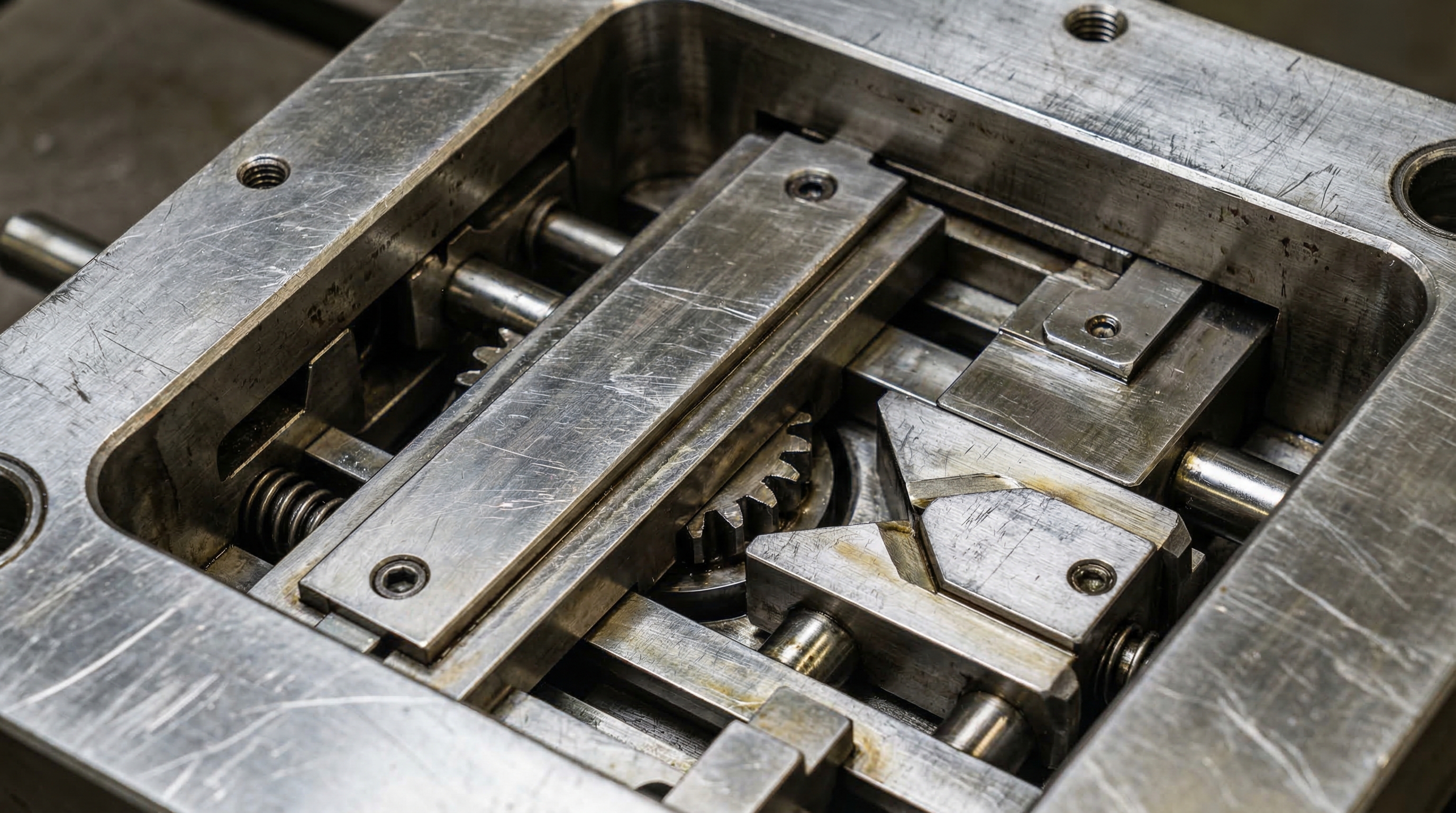
Side-actions are mechanical components that slide into the mold cavity to form undercuts and retract before the part is ejected. In the context of undercut injection molding, these “cams” are indispensable for creating internal holes, slots, or external threads that cannot be handled by the parting line. They allow for the creation of complex tubular shapes and functional side-ports in medical or automotive housings.
How do side cams operate?
Side-actions typically use an angled pin that pulls the cam away from the part as the mold opens. This automated process ensures that the undercut is cleared before the ejector pins push the part out of the cavity.
The best part? You get fully automated production for parts that would otherwise be impossible to mold.
- Use side-actions for deep external side-holes.
- Ensure the cam has enough travel to clear the feature.
- Keep the side-action width within machine limits.
Key Takeaway: Side-actions provide the freedom to design functional, complex features while maintaining the speed of an automated injection cycle.
| Tooling Element | Function | Material Suitability | |
|---|---|---|---|
| Angled Pin | Drives the motion | Rigid plastics | |
| Cam Slide | Forms the undercut | Most resins | |
| Locking Block | Holds cam during high pressure | All |
Automated side-actions are the gold standard for high-precision, high-volume B2B part production.
When are bumpoffs used in undercut injection molding?
Bumpoffs are used for shallow, rounded undercuts where the material is flexible enough to stretch over a mold protrusion during ejection. This technique for undercut injection molding is common for container caps, snap-fits, and lens covers. It relies on the “elastic memory” of the plastic to return to its original shape after being forcibly pushed off the mold core.
Which materials are best?
You must select resins with high elongation and flexibility to prevent the part from tearing or whitening during the “bump” process. Materials like TPE, TPU, and LDPE are ideal candidates for this specific maneuver.
Here is the kicker: If your material is too rigid, the part will simply crack.
- Ensure the undercut has a generous radius.
- Maintain a shallow depth for the feature.
- Verify that the part has room to expand during ejection.
Key Takeaway: Bumpoffs eliminate the need for moving mold parts entirely, provided your design and material choices support the required temporary deformation.
| Feature Property | Requirement for Bumpoff | Result | |
|---|---|---|---|
| Edge Profile | Smooth, well-radiused | Prevents tearing | |
| Undercut Depth | Shallow (typically <5-10%) | Allows expansion | |
| Resin Type | Flexible/Elastomeric | Ensures recovery |
Successful bumpoffs depend heavily on the intersection of geometry and polymer physical properties.
Why use hand-loaded inserts in undercut injection molding?
Hand-loaded inserts are used when a feature is too complex for side-actions or when production volumes don’t justify the cost of expensive automated tooling. During undercut injection molding, an operator places a metal piece into the mold before each cycle, which is then ejected with the part and manually removed. This method is highly effective for low-volume prototypes or parts with very deep, internal undercuts.
Is manual labor worth it?
While this increases the cycle time, it significantly reduces the upfront investment in mold design and construction. It offers a bridge between low-fidelity prototypes and high-volume automated production.
Check this out: You can achieve complex internal threads without a $20,000 unscrewing mold.
- Use for prototyping complex internal geometries.
- Ensure inserts are large enough for safe handling.
- Provide multiple sets of inserts to keep the machine running.
Key Takeaway: Hand-loaded inserts are a tactical choice for low-volume runs, allowing for extreme design complexity without a massive capital outlay.
| Tooling Method | Cycle Time | Tooling Cost | |
|---|---|---|---|
| Hand-Loaded Insert | Slower (Manual) | Low | |
| Side-Action Cam | Fast (Auto) | High | |
| Collapsible Core | Very Fast (Auto) | Very High |
Balancing labor costs against tooling investment is critical for short-run manufacturing success.
How do telescoping shutoffs aid undercut injection molding?
Telescoping shutoffs allow you to create holes or windows in the side of a part using only the main mold opening motion. By utilizing this method in undercut injection molding , two halves of the mold meet and “shut off” the flow of plastic to create a void. This is commonly used for clip-style fasteners and snap-fits where a side-action would be overkill.
What about draft angles?
You must include a minimum of 3 to 5 degrees of draft on these shutoff surfaces to prevent metal-on-metal galling. Without proper draft, the mold components will wear out quickly, causing flash and part defects.
Here is the deal: Draft is not a suggestion; it is a requirement for tool longevity.
- Design a “hole” in the part base to allow the mold half to reach through.
- Use enough draft to ensure clean separation.
- Align the shutoff parallel to the mold opening direction.
Key Takeaway: Telescoping shutoffs are an elegant design solution that replaces moving cams with clever geometry, drastically lowering maintenance costs.
| Design Feature | Purpose | Critical Factor | |
|---|---|---|---|
| Through-hole | Allows mold reach | Placement | |
| Shutoff Face | Blocks plastic flow | Draft angle | |
| Alignment Pin | Ensures precision | Tolerance |
Smart geometry choices often prove superior to mechanical complexity in mold engineering.
Can secondary ops improve undercut injection molding?
Secondary operations involve machining features like holes or threads into a part after it has been ejected from a simple mold. In many undercut injection molding scenarios, it is actually cheaper to drill a side-hole than to build a complex mold with a side-action. This is especially true for small production batches where the cost-per-part of a complex mold would be prohibitively high.
When should you machine?
You should consider secondary operations if the undercut is extremely small, placed at an awkward angle, or if you only need a few hundred parts. Standard CNC machining can quickly add features to a “blank” molded part with high precision.
Believe it or not: Sometimes the most “high-tech” solution is a simple drill press.
- Compare the cost of secondary labor vs. mold amortization.
- Ensure the molded part has enough wall thickness for machining.
- Use fixtures to ensure consistent feature placement.
Key Takeaway: Secondary operations provide a fallback for designs that are otherwise “unmoldable” or too expensive to automate in the short term.
| Production Volume | Preferred Method | Reasoning | |
|---|---|---|---|
| 1 – 500 units | Secondary Machining | Low tooling risk | |
| 500 – 5,000 units | Hand-loaded Inserts | Balanced cost | |
| 10,000+ units | Fully Automated Cams | Lowest per-part cost |
Post-molding modifications offer a flexible safety net for complex engineering requirements.
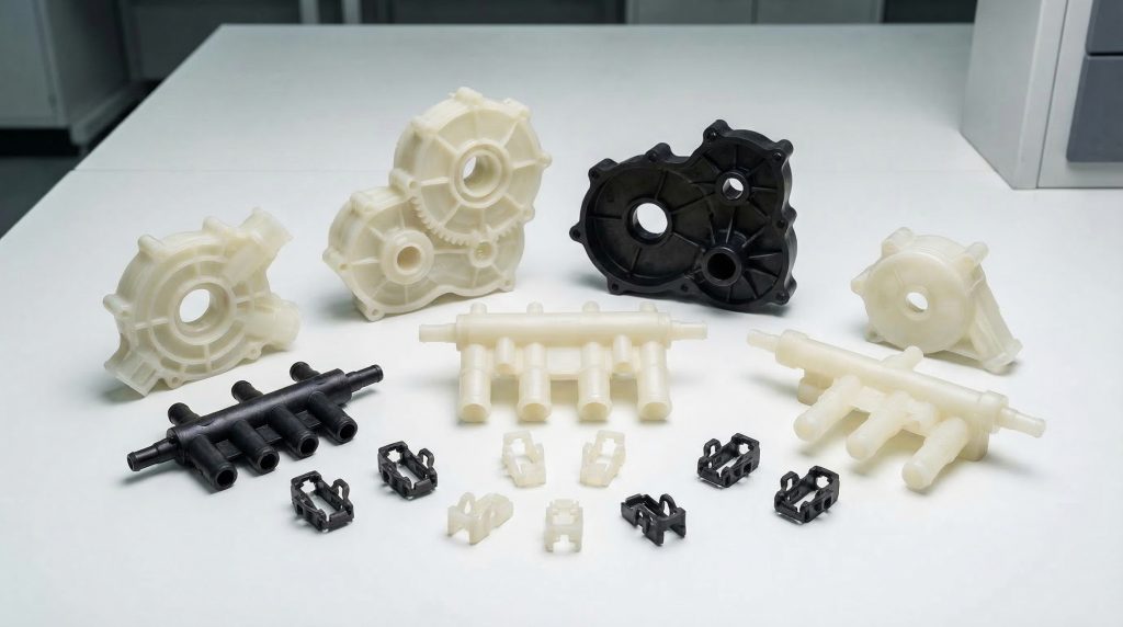
What materials work for undercut injection molding?
Material selection dictates how well an undercut can be formed and whether it will survive the ejection process without damage. When choosing resins for undercut injection molding , you must balance mechanical strength with the specific requirements of your ejection method. For example, a rigid Glass-Filled Nylon is excellent for side-actions but will fail catastrophically in a bumpoff design.
Does shrinkage matter?
You must account for material shrinkage, as undercuts can “grip” the mold core as the part cools. If the material shrinks too much, it can become trapped on a side-action or internal pin, leading to part deformation.
The bottom line: Your material choice is the silent partner in your mold’s success.
- Use rigid polymers (PC, ABS, Nylon) for side-action features.
- Opt for elastomers (TPE, Silicone) for complex bumpoffs.
- Check the resin’s data sheet for specific elongation limits.
Key Takeaway: Matching your material’s physical properties to your chosen undercut ejection method is the only way to ensure consistent quality.
| Material Class | Elongation | Best Undercut Method | |
|---|---|---|---|
| Thermoplastics | Low to Medium | Side-actions / Shutoffs | |
| Elastomers | High | Bumpoffs / Hand-loads | |
| Liquid Silicone | Very High | Complex Bumpoffs |
Correct material pairing prevents expensive “stuck part” scenarios during the production ramp-up.
Does DFM analysis save undercut injection molding?
Design for Manufacturability (DFM) analysis is the process of reviewing a part design to catch undercut issues before the mold is ever cut. Effective undercut injection molding relies on these digital simulations to identify “trapped” areas and suggest potential fixes. A professional DFM report will highlight every area where the part cannot be ejected by a straight-pull mold.
How do you use the report?
You should view the DFM report as a roadmap for optimization, not just a list of problems. It provides a visual guide to where you need side-actions, draft increases, or parting line shifts.
But wait: Don’t just ignore the red highlights; they represent real-world failures.
- Review the “trap” maps provided by your manufacturer.
- Adjust wall thicknesses to ensure uniform cooling around undercuts.
- Validate that all side-action features have sufficient clearance.
Key Takeaway: DFM analysis is your primary insurance policy against mold rework and delayed product launches.
| DFM Checkpoint | Issue Detected | Suggested Fix | |
|---|---|---|---|
| Draft Analysis | Inadequate release | Increase angle | |
| Undercut Map | Trapped feature | Add side-action | |
| Sink Analysis | Thick sections | Core out material |
Proactive digital reviews are the most efficient way to de-risk complex molding projects.
How to optimize costs for undercut injection molding?
Cost optimization is the art of balancing part functionality against the mechanical complexity of the mold. In the final phase of undercut injection molding , you must decide if the performance gain of a complex feature justifies its impact on the piece-part price. Often, consolidating multiple small undercuts into one larger side-action can save significantly on tooling costs.
Can you group features?
You should look for opportunities to place multiple side-holes or slots in a single plane so they can be handled by one side-action cam. This reduces the number of moving parts in the mold and lowers the overall maintenance burden.
Here is the deal: Every extra moving part in a mold adds a potential point of failure.
- Minimize the total number of side-actions per mold.
- Choose standard component sizes for your cams and pins.
- Consider multi-cavity molds only after the undercut design is proven.
Key Takeaway: Strategic grouping and the clever use of shutoffs can drastically reduce the “complexity tax” often associated with advanced part designs.
| Cost Driver | Influence | Mitigation | |
|---|---|---|---|
| Number of Cams | Very High | Group features into one plane | |
| Manual Labor | High | Automate for high volumes | |
| Mold Maintenance | Medium | Use shutoffs instead of cams |
Economic success in molding depends on engineering out as much mechanical movement as possible.
Summary of Undercut Success Strategies
Mastering undercuts is the difference between a project that stalls and one that scales. At CN Precision Manufacturing, we specialize in navigating these complex geometries to provide you with high-precision components that meet your exact specifications. Whether you need a 48-hour DFM review or a full-scale production run for automotive or medical applications, our 15+ years of expertise ensure your parts are optimized for cost, quality, and speed. Our commitment to IATF 16949 standards means you receive German-level quality with the competitive edge of Shenzhen efficiency. Stop compromising on your designs and start manufacturing with confidence.
To get your project started with a professional DFM review and a competitive quote, contact us today .
Frequently Asked Questions
Can I use undercuts for internal threads in high-volume production?
Yes. For high volumes, the best way is to use an automated unscrewing mold or a collapsible core. These mechanisms are expensive to build but provide the fastest cycle times and best thread quality for thousands of parts.
What’s the best way to handle a deep side-hole that needs to be watertight?
The best way is a precision-machined side-action cam with a locking block. This ensures the core pin remains perfectly seated under high injection pressure, preventing flash and ensuring the hole meets strict dimensional tolerances for a seal.
How do I know if my material is flexible enough for a bumpoff?
The best way is to check the “Elongation at Break” value on the material data sheet. Generally, materials with an elongation greater than 100% can handle shallow, well-radiused bumpoffs, while rigid materials with low elongation will fail.
Can I have undercuts on both the inside and outside of a part?
Yes. The best way is to use a combination of internal lifters for the inside and external side-actions for the outside. This increases mold complexity significantly, so you should only do this if the part geometry cannot be simplified through DFM.